Opening Safes by Manipulation
Mechanical combination safe locks have been used for over a century. The example for this article will be a Sargent and Greenleaf (S&G) safe lock, but most other brands will have similar basic construction.
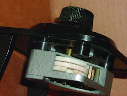
Most safe locks usually consist of three or four wheels (called a wheel pack) which each rotate on a single rigid post in the lock case. Each wheel contains projections which form the connection between each wheel. Each wheel also contains a notch on its outer edge (figure 1).
The safe dial is connected to a spindle. The spindle extends into the lock case through the hollow post. A drive cam is attached to the end of the spindle. The drive cam also contains a drive pin projection. During one complete rotation of the safe dial, the drive cam pin projection will contact the projection of the adjoining wheel and that wheel will begin to rotate in unison with the drive cam. During each succeeding revolution of the safe dial, the projection of the next adjoining wheel will be contacted and that wheel will also will begin to rotate.
Most safe locks contain a lock bolt. When the lock bolt is extended, the safe cabinet boltworks are prevented from moving. A spring-loaded lever is connected to the lock bolt which controls lock bolt movement. The lever contains a narrow bar called a fence. The fence rests on the outer edges of the wheel pack. When the correct sequence of numbers is dialed, notches in each wheel are aligned at the fence location (figure 2). The spring-loaded fence will then enter the groove made by the notches and continued rotation of the drive cam will move the lock bolt to the unlocked position (figure 3).
Manipulation depends on the extra tolerances machined into every safe lock because of mass production. Instead of having to hand-fit each part during assembly, parts such as the shaft screw retaining the lever are made a few thousands smaller than needed to assure that any chosen lever and screw will easily operate together. During manipulation, this added looseness allows the lever to tilt slightly which provides indicators which can be used to determine the safe combination.
A second factor in manipulation is the outside operating diameter of individual wheels. Variations in the outer diameter of each wheel or variations in the wheel hole diameter can help the manipulation process.
If the outside operating diameter of one wheel is slightly higher than the remaining wheels, the notch in that wheel will be more easily identified during manipulation.
Preparing for Manipulation
You can either mount a safe lock on a board and remove the lock cover while practicing or you can order a cutaway practice lock and mount as shown in our photos. Lockmasters sells an S&G cutaway lock, part number SG6730CUT, and a LaGard cutaway lock, part number LAG3330CUT. Call Lockmasters at 800-654-0637 for further information.
First, determine the two contact points for the drive cam. These two points are where left and right edges of the drive cam notch touch the lever. Figure 4 shows the contact point when turning the dial counter-clockwise (left) and figure 5 shows the contact point when turning the dial clockwise (right).
When the dial is turned to the left, the contact dial reading for this example lock is 13 (figure 6). When the dial is turned right, the contact point is between a 6 and 7. The right turn reading is approximately 6 1/4.
The 1/4 distinction is important because in order to manipulate a safe lock, you must note the small changes between marks such as 1/4, 1/2 and 3/4. Contact points will vary on individual safe locks depending on what quadrant the drive cam was attached to on the spindle.
In order to expand readings over a wider area, a homemade pointer tool was developed (figure 8). It was made from a suitable plastic plumbing cap, a two-inch hose clamp and a bent length of coat hanger wire. The plumbing cap was enlarged on the inside slightly to fit over the dial ring. Slits were sawed into the end cap to allow the clamp to compress and tighten both the pointer and the end cap around the dial ring (figure 9). A sheet metal plate was fastened under the dial ring to hold paper for marking (figure 10).
More elaborate manipulation tools are available but this is a low cost way to begin practice. In a real manipulation situation, the length of the pointer is only restricted by other obstructions on the safe such as the safe handle. The longest possible pointer provides the widest and most easily noticed variations during readings.
You will also need some pages of graph paper. This S&G lock dial contains numbers from 1-100. Mark the graph papers so that each vertical line represents 2 1/12 numbers. Therefore you will have 40 vertical lines. Choose any horizontal line on the mid-point of your graph paper and mark it as your Left contact point. (In our example the Left contact point was at 13). Above the horizontal line mark additional horizontal lines with 13 1/4, 13 1/2, 13, 3/4 Below the "13" horizontal line mark additional horizontal lines with 12 3/4, 12 1/2 and 12 1/4.
First, turn the dial to the left at least 4 revolutions and stop at "0". Now quickly turn the dial to the right one revolution. As you approach "0" you should feel and hear the drive cam "pick up" the wheel adjacent to the drive cam (3rd wheel in a three wheel pack). Continue turning quickly through a second revolution. As you approach "0" again you should feel and hear the 3rd wheel as it "picks up" another wheel (2nd wheel in a three wheel pack). One more revolution and the same sound and feel should be noticed as you "pick up" the 1st wheel. Any further dial revolutions should not show any difference in the sound or feel. You have now determined that there are three wheels (and combination numbers) in your lock.
The next step is to use a small probe or screwdriver and align one of the wheel notches under the fence. Then take a reading and note any difference in the drive cam contact points. There was little change when testing the 1st and 3rd wheels, but in our sample, the 2nd wheel showed a visible change in the contact reading.
Obviously in this case the 2nd wheel is larger enough as compared to the other two wheels to allow the fence to move in slightly when the notch is aligned with the fence. Contact readings will change because the lever tip has moved slightly deeper into a wheel notch.
Beginning Manipulation
- Turn the dial Left at least four complete revolutions and stop at "0". .
- Continue turning the dial Left and stop at 2 1/2
- Turn the dial right to the contact point and record the reading on your chart. The right contact point (highest number) normally provides the largest change during each reading).
- Add 2 1/2 to the number in Step 2 and turn the dial left to that number.
- Turn the dial right to the contact point area record the reading on your chart.
- Continue with steps 4 and 5 until you reach 100.
Your chart should show a noticeable 'dip' somewhere in the charting . The dip indicates when the notch of one of the three wheels was aligned near the fence. For an example, we will say the dip was at 45. The next procedure is to determine a more precise reading by concentrating on the numbers near 45 by dialing one number at a time and plotting the results again. In this example we will concentrate on the numbers from 43 to 47.
Step 7. Turn the dial left at least four revolutions and stop at 43.
Step 8. Turn the dial right to the contact point and record the reading on your chart.
Step 9. Add '1' to the number in Step 8 and turn the dial Left to that number.
Step 10. Turn the dial right to the contact point and record the reading on your chart.
Step 11. Continue with steps 3 and 4 until you reach our example of 47.
Your chart should show a more precise graph line again with a pronounced dip at one number. As example, the dip is at 46. You have now determined one of the combination numbers.
Determining the Indicating Wheel
Step 12. Turn the dial left at least four revolutions and stop at 46 (for this example).
Step 13. Turn the dial right one revolution, 'pick up' the 3rd wheel at 46 and continue approximately 10 numbers farther (to 36). The 3rd wheel has now been purposely set away from our example number of 46.
Step 14. Turn the dial left to the contact area and take a reading.
If the contact reading is low, this indicates that the notch from either the 1st or 2nd wheel remains aligned under the fence and one of those two numbers have a combination number of 46. If the reading is high, this indicates that the 3rd wheel, which is now out of position, had the original low reading and therefore the third wheel number is 46.
If it is determined that the third wheel provided the low reading, then proceed to "Manipulation Continued." Otherwise go to Step 15.
Step 15. Turn the dial left at least four revolutions and stop at 46 (for this example).
Step 16. Turn the dial right two revolutions to pick up both the 3rd and 2nd wheels. Continue 10 numbers past 46 (36 in our example) and stop.
Step 17. Turn the dial left to the contact area and take a reading.
If the contact reading is low, this indicates that the notch from the 1st wheel remains aligned under the fence and the 1st wheel has a combination of 46. If the reading is high, this indicates that the 2nd wheel, which is now out of position, had the original low reading and therefore the 2nd wheel number is 46.
Manipulation Continued
Use a new chart paper and repeat steps 01-06. Dialing revolutions are determined by which wheel was discovered to contain our example combination of 46. That wheel must be dialed to the operating number (46 in our example) while the remaining two wheels are dialed by adding 2 1/2 number at a time from 1 to 100. Note each contact number on the chart paper and again look for a "dip". As example: if the dip is now showing at 85, dial single steps (from 83 to 87 for our example) and chart the contact points. As example, the second combination number was determined to be 86.
Once you have two numbers of the combination and know which wheels contain the numbers, the final step is to rotate the final wheel by dialing the two known combination numbers and adding 2 1/2 to the unknown wheel until the last wheel notch is aligned under the fence by trial and error. You are done when the safe lock unlocks.