Tech Tips: Programming the Essex SKE 34 and SKE 26 Standalone Keypads
The Essex SKE-34 and SKE-26 heavy-duty self standalone keypads have many great features. They do not produce an audit trail, nor can they be remotely programmed, so they are not suitable for applications where these features are required. On the other hand, they cannot be hacked by some ragger with a smartphone.
The SKE 34 is a 3 x 4 type keypad and the device mounts on a single gang box. The SKE 26 is a narrow 2 x 6 type keypad which is good for mullions on a storefront. Wiring and programming is the same for both the SKE 34 and the SKE 26.
With storefront type installations, the wall adjacent to the door is typically either more glass or brick, so mounting the keypad on the mullion may make running your cables easier than if you mount it on brick.
The unit has an integral Form C (SPDT) 2Amp main output relay, as well as two open collector outputs which can operate exterior relays and be controlled in a variety of ways.
Open collector refers to an output which is the collector of a transistor, and the open collector switches to ground when that output is activated. You can connect this output to a low current relay coil or other low current draw load.
The outputs can be configured several different ways, but using the main output which is rated at 2 amps and therefore can switch many kinds of electric strikes and electromagnetic locks is the usual practice.
I use the outputs from devices like the SKE 26 to operate a isolation or slave relay first which in turn is connected to the actual load. This reduces the wear and tear on the internal relay, and provides immunity if the electric lock produces electronic noise or small spikes when the lock energizes. By using an isolation relay, you also offer a degree of isolation to the circuits inside the keypad from power surges or lightning.
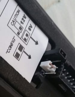
SKE 34 and 26 may be configured to operate at 5 VDC or 12/24VDC. All external connections are through a multi conductor plug which attaches to the rear of the keypad and is concealed when the keypad is mounted.
Since the ESSEX relay and outputs are used to control locks, it is sometimes conjectured that removing the keypad from the wall exposes the wires, which could then be used to unlock the door. This is prevented by using a technique alarm installers used on their shunt keyswitches. Once the keypad is mounted, pull and slack in the cable to inside the premises and securely anchor it. Then if the keypad is pulled off the wall, the cable will remain in the wall and the connections will remain inaccessible.
These keypads are programmed using the keypad, and not a computer or external device.
For one application, I used the main output to operate an electric lock, and I used Output A to operate something else, using a separate distinct code. We used the third output (Output B) to turn on a camera for whenever someone began making entries into the keypad. This third output is preconfigured in the default set up of the keypad to activate, but it is easily reconfigured if desired.
I got three relays and a plug-in 12 volt power supply and wired them so I can easily program and then test each keypad before getting to the job site.
There is a comprehensive manual included with every keypad which includes programming and wiring, but I’ve found it less confusing to write out a script of what I am programming into the keypad rather than have to thumb through pages in the booklet while programming.
To change the master code from the default (1-2-3) to something else (0816):
Enter * 3 and the master code followed by pound (* 3 1 2 3 #)
Enter 1# and the new master code followed by pound (1#0816 #)
Enter * * to exit programming.
The main relay should activate when you enter 0816#. Then you are ready to program user codes.
If you mess up programming and get lost, or do not know the master code, it will be necessary to remove the keypad from the wall to do a reset.
- Remove keypad from wall
- Unplug the harness to remove power from the keypad
- Place a jumper between the two pins labeled “config”
- Reconnect the harness. There will be 4 beeps. red LED flash, green LED solid.
- Enter 0099#. Two beeps should sound, then both LEDs flash for 10 seconds. Wait until you hear 4 beeps and see the red LED flash and green LED solid.
- Enter 99#
- Unplug the harness to remove power from the keypad
- Remove the jumper from “config.” (park the jumper for the next time).
- Plug the harness back in. The red LED will light up on the front of the keypad.
- Default master code 1-2-3 # should now work. (It may not work the first time you enter it so try again, and then it will.)
The manual has lots of programming options, and if you get lost, you can call the factory.
About the Author
Tim O'Leary
Tim O'Leary is a security consultant, trainer and technician who has also been writing articles on all areas of locksmithing & physical security for many years.
