LCN 6400 COMPACT Installation, Part 2
In November 2022, we discussed the installation of an LCN 6400 COMPACT door operator where no electronic access control (EAC) was necessary. In this article, we’ll discuss an EAC installation, including wiring up the power supply and electric strike in addition to the door operator.
As a reminder, the 6400 COMPACT is a low-energy door operator. If you play with low-voltage wires and your state requires low-voltage licensing, you have to have the proper licensing before you start.
This installation was performed at a local library. Once again, I worked with John Nolan from Reliant Security, who is a wiring specialist, for this installation, and, once again, the ease of installation makes the 6400 COMPACT a great product for locksmiths.
Locating the Hardware
After the door closer and operator are installed, we plan the location of the power supply. It should be mounted out of the way where people generally can’t come in contact with it. These power supply boxes also are equipped with a key lock, so it’s a good idea to keep them locked when they aren’t being serviced. Also, think about your wiring. The straightest wire runs will be the best.
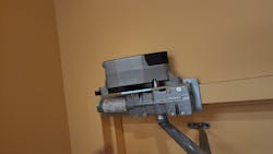
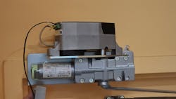
We decide to mount the power supply over the door, keeping it near to the door operator and in line with the door jamb for a symmetrical installation. (Image 2) This location also makes for a short and direct wiring line to the electric strike. After drilling holes into the wall and frame, we’ll be able to connect the door operator as well, with all wire hidden from view.
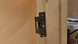
The existing mechanical strike is removed for our electric strike. The new strike will be an LCN NC450, a no-cut model that doesn’t require much, if any, modification. (Image 3) We didn’t have to modify the strike box to fit the strike and its wiring connection “pigtail.” A one-half-inch drill hole through the box into the frame typically is enough to get the connector into the frame after we connect the wires. (Image 4)
Planning the Wiring
For the wiring from the strike to the power supply, we fish wire tape from the strike plate up through the door frame and out the top where we will mount the power supply. I use a pair of forceps for this. When you’re pulling wire, these tools, or long needle-nose pliers, are essential tools to have. Then, we apply the 18/2 unshielded wire to the tape and run it back down. The 6400 COMPACT requires 18/4 wire to account for accuation, and we run that through the door frame between the power supply and door operator.
At this point, we’ll mount the power supply, using heavy-duty wall anchors. A good piece of advice is to use an extended drill bit so you can mount the power supply without the drill hitting and scuffing the power supply box.
Our power supply is a Schlage Series 900. The instructions include a wiring diagram for mapping an EAC wiring run, but you also have to look at the wiring diagrams for the other pieces to make sure the wiring syncs. One of the most important things to remember about an EAC installation is that when you pair an electronic strike with a door operator, make sure that they’re wired in the correct order. It’s the only way that you will be able to get them to work with one another. The electronic strike has to release first for the door operator to open the door.
I’ve found that taking the time to map out the wiring ahead of time provides for a better install. One could compare it with rekeying a lock or master keying: If you write out your plan of action ahead of time, there will be less chance of error when you put it together.
Wiring the 6400 COMPACT
Remember, be careful when you strip the wire. You never want to strip any wire too far back, because you could have a connecting issue. However, you also have to make sure that enough copper is exposed to make the connection in the block. A “jumper” is included in the 6400 COMPACT kit and, again, all wires, including the jumper, must be in the correct order according to your application. The power wires were connected to terminal Nos. 1 and 2 in our installation, while the actuator wires went to terminal Nos. 4 and 5. The motor switch for the 6400 COMPACT goes in terminal Nos. 7 and 8, so the jumper then is installed on terminal Nos. 6 and 9.
The wires are wound tightly in their individual locations to ensure that when they’re screwed down in the wiring block, they can’t come loose or possibly touch or arc. After this step is complete, the wiring terminal block can be plugged back into the 6400 COMPACT. (Image 6)
Wiring the Power Supply
Our power supply has field-selectable power, and our receiver requires 24 volts of constant power to run, so we select the correct power and connect the wires from the receiver to the correct power board. At the same time, we connect the power wires from the 6400 COMPACT. Take note of how the wire colors coordinate.
As is the case when connecting wires to the door operator terminal block, make sure your power supply wires are stripped to the correct depth before you tighten them down, so they make a good connection and don’t short out.
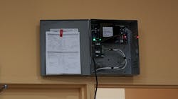
When you embark on this type of project, be aware that instructions can be taped and left in the power supply. We also always write the date and the power selected on the inside of the power supply, so it’s known when it was installed and what the power is.
Then, we follow the wiring map that we sketched out earlier to make all the connections for operation among the components. We connect the door operator first, followed by the strike and the receiver. More hook-and-loop tape can tie up the loose wires in the power supply for a professional look. (Image 7)
The Final Pieces

After connecting the two ends, we apply more tape around the connectors. This helps to hold them together while providing more protection before we pull them through the predrilled hole in the door frame.
Our door has a deadlatch, so to account for that, we drill a one-eighth-inch notch into the frame before we install the strike. Always check to make sure you have a good close.
The ADA-compliant push-button is installed on the banister adjacent to the outswing door. (Image 9) It’s a solid mounting place and is between the 36-inch and 48-inch specifications for Americans with Disabilities Act requirements.
We then attach the cover to the 6400 COMPACT to complete the project. An electrician will come and bring 120-volt hard power and conduit to the power supply. (Image 10)
Wayne Winton is the owner of Tri-County Locksmith Services, located in Glenwood Springs, Colorado. Scan the QR code to watch a video of the complete installation.
About the Author

Wayne Winton
Wayne Winton, CRL, AFDI, CAIis the owner of Tri-County Locksmith Services, located in Glenwood Springs, Colorado, and the president of the ALOA Security Professionals Association.