Von Duprin was started in 1908, when, according to Ingersoll Rand, it introduced the first “panic release bar” in response to a need for protecting life safety while providing security. Indianapolis hardware salesman Carl Prinzler missed a scheduled visit to Chicago’s Iroquois Theatre in 1903, escaping the disaster where 594 people perished when the “fireproof” theater burned.
Obsessed with the needless loss of lives, Prinzler was determined to solve the problem of public buildings that often turned into death traps when doors were locked to keep gate crashers out. Prinzler teamed up with Henry DuPont, an architectural engineer, who invented the first working device.
The initial model was marketed by Vonnegut Hardware Company under the name Von Duprin, a contraction of the words Vonnegut, DuPont and Prinzler.
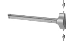
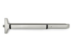
For more than 100 years, Von Duprin has been manufacturing exit devices. The 88 Series crossbar exit devices still manufactured by Von Duprin have similar appearance characteristics to the original design, although there have been significant engineering advancements.
Jumping ahead to the 1970s, almost 40 years ago, Von Duprin introduced electric latch (EL) retraction for specific models of their pushbar exit devices. The electric latch retraction provides remote access control using a power supply and switch mechanism. When power is provided, the solenoid retracts, pulling the latching mechanism to the unlocked position, while at the same time, retracting the pushbar. Mechanical egress is always available by pressing the pushbar when the latching mechanism is engaged.
With the introduction of the Quiet Electric Latch (QEL), latch retraction has evolved from solenoid operation to motor operation and gained the benefits of computerization. The motorization of Von Duprin exit devices provides the added benefit of quieter operation both electrically and mechanically.
Some of the computerized features of QEL include troubleshooting diagnostics, automatic calibration, retry mode and vandal resistance/detection. The QEL automatic calibration adjusts the latch throw and pull to accommodate installation variables, minimizing the need to adjust vertical rod latches. The retry mode makes a second attempt to retract the pushbar if the first is not successful. If the exit device detects the pushbar being repeatedly pulled on, the QEL equipped exit device will “play dead” for five minutes.
Like the EL, the QEL mechanism pulls, causing the pushbar and the latch bolt to retract, providing access. The delay time is on-board adjustable. The QEL mechanism can be electrically dogged to provide electronic passage mode. Passage mode can be activated via key switch or access control system.
The Quiet Electrified Latch option is available with new 98/99 series (including XP), 33a and 35a Series UL Listed panic hardware and fire exit hardware. The QEL conversion Kit is UL Classified under “Accessories for Single-Point Locks and Latches and Fire Exit Hardware” (UL 10C).
QEL conversion kits are motorized baseplate assemblies designed to replace the exit device’s existing baseplate assembly. Two Von Duprin QEL Conversion Kits for retrofit applications are UL Classified for UL10C. One kit is for a three-foot exit device and the other kit is for a four-foot exit device.
Note: If you are upgrading from an EL-equipped device, be sure to disconnect the AC power before removal. If the exit device has battery backup, unplug all of the wires from the battery terminals.
For the purpose of this article, we retrofit a non-electrified Von Duprin 98 Rim exit device, which has the non-ribbed case. To install the new baseplate, the exit device must be removed from the door and partially disassembled in order to remove the control link pin and two Phillips head screws securing the baseplate to the center case.
Step 1. Remove the exit device from the door by removing the four Phillips head cover screws and two end cap screws. Remove the cover and the end cap. Slide the cover plate off.
Step 2. Remove the two Phillips head screws securing the end cap bracket to the door. Remove the end cap bracket.
Depending upon the original installation, there could be two mounting screws along the front of the center case just above and below the Pullman Bolt. These mounting screws are designed to secure the center case onto the door to simplify installing exterior trim. (See Photo #16)
Step 3. Remove the mounting screws securing the center case to the exterior trim. Carefully remove the trim from the exterior of the door. Up to four of the mounting screws can be used to secure the center case to the trim.
If the exit device is equipped with the two mounting screws adjacent to the Pullman Bolt, unscrew them in order to remove the exit device from the door.
Step 4. Place the exit device onto a flat surface. If equipped, remove the two mechanism case bracket 5/16” bolts securing the center case to the mechanism case. These bolts had a straight screwdriver slot within the head. Remove the bracket from the center case.
Step 5. Slide the mechanism case off the exit device.
Step 6. Remove the pushbar from the baseplate by lifting the pushbar up and forward while moving the forward pushbar guide down. The black plastic pushbar guides are designed to direct the pushbar’s movement. They are mounted onto the front and rear of the pushbar. Lift the pushbar off the baseplate when free.
Step 7. The center case is attached to the baseplate by two Phillips head screws from the bottom and the control link pin. Remove the two screws, clip and pin.
Step 8. Attach the QEL baseplate to the center case using the two screws, the clip and the pin.
Finish assembling and then install the exit device onto the door.
Only two wires are required to power/operate the QEL baseplate for up to a 200-foot wire run from the power supply to the QEL. The wire gauge can be a minimum of 18 AWG. Von Duprin recommends two lead stranded wire.
The QEL operates in conjunction with the 871-2Q logic board that is plugged into the Von Duprin PS873 Power Supply. This power supply provides 4 Amps @ 12VDC and 2 Amps @ 24VDC. A PS873 power supply will support up to four QEL equipped exit devices.
Note: For upgrades, the EL board can be removed and the 871-2Q logic board can be installed into the power supply.
The Von Duprin Quiet Electric Latch is available for 98, 99, 35a and 33a series devices excluding CheXit, EL and ALK. It is not available with mechanical or cylinder dogging.
For more information, contact your local locksmith distributor or Von Duprin, Web site: www.vonduprin.com.
For additional Locksmith Ledger articles on Von Duprin products, visitwww. tinyurl.com/vonduprin0710.
http://tinyurl.com/vonduprin0710


