Welcome to the new Locksmith Ledger Back to the Basics series. Today we’re going back to the very beginning. We will rekey a pin tumbler lock cylinder.
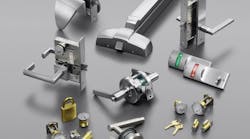
First we will identify the parts: the plug, the housing, bottom pins or key pins, top pins or driver pins, springs, spring cover, C-clip, retaining cap and tailpiece.
Photo 1 shows a cutaway cylinder. If you are doing any kind of rekeying, I highly recommend you invest in a cutaway cylinder. You can literally work right along with us as we go through the video and the cutaway gives you an extremely good visual aid.
The first thing we need to do is identify the type of keyway and lock cylinder. This (Photo 2) is a Schlage or SC1 or SC4 key blank. The difference between the two is that SC1 is a five-pin key and SC-4 is a six-pin key. Make sure that you have a working key and test the key.
In photo 3, I am showing a capscrew removal tool and in Photo 4, we have pinning tweezers. Pinning tweezers have a little notch at the end of the tweezers to allow the pin to be grabbed with the tweezers, so the pin does not rotate or fall out when you’re trying to insert it into a lock. It actually grabs the pin and holds it firmly in place.
Tip: If you need to make your own pinning tweezers, use a Dremel-style tool with a tile-cutting carbide bit that is pretty much the same diameter as the pins. I turn on my high speed tool and pinch the tweezers directly into it. This will grind out that little groove about the same size or diameter as the pin.
Another tool you’ll need is a Phillips head screwdriver, along with a flat-head screwdriver and a good pivot file. A good pivot file is usually imported from Italy or Switzerland.
Photo 5 shows the Pro-Lok KD01 key gauge. I recommend having at least one key gauge, if not more. You’re going to need a key gauge at some point in time.
Note the series of numbers written on the key. These numbers will correlate with the cuts of the key in most cases. This isn’t always true, so this is where a key gauge comes into play. The key gauge will verify that those cuts are correct.
To begin rekeying this lock, the first thing that we need to do is identify the retaining pin (Photo 6). Then we push the retaining pin in to remove the cap or capscrew that I have in my hand (Photo 7) and the tailpiece .
This tailpiece has two different notches to go in two different positions. The retaining pin is now touching my index finger (Photo 8) and is spring-loaded. Be very careful at this point to make sure that this retaining pin (also referred to as a detent) does not go flying off into the abyss. Making sure that we have everything over the pinning mat is essential.
Photo 9 shows the retaining cap pin spring that drives that pin into the retaining cap, not to be confused with a key pin spring. The key pin spring is much larger and much thicker than a retaining cap spring.
Photo 10 shows the hole the retaining cap pin spring goes into. Now we have everything removed from the back of the lock cylinder, so we can insert the key. I like to rotate 90 degrees away from the housing or the top or the bible of the lock. In most cases, that will work.
Depending on what kind of tailpiece you have (there are different shapes), make sure it is rotated in a way such that there will not be a gap created when you use the follower to push the plug out of the lock housing. I emphasize pushing. You never want to pull on the cylinder. That will make the top pins explode into the housing and you’ll have to rebuild that cylinder.
Notice there’s no space between the follower that’s in my hand (Photo 11) and the plug that’s on the other side.
We will insert the new key. We verified that that the number one and number two positions (number one and number two cuts) are completely different from the original key. I always recommend putting in the new key to make sure that it is different and verify that beforehand.
Photo 12 shows a Lab 03 pinning kit. This is a well-used 3,000 professional pinning kit with a lot of pins added, so there are some pins that are red, which is an 05 pinning kit color in an 03 pinning kit. (Photo 13) Don’t pay attention to the colors right now. The pins are the accurate sizes.
This is a number 3 pin, 210-thousandths, and then the final position will take this number 9 cut or 300-thousandths bottom pin (Photo 14).
Now - the entire cylinder has been rebuilt (Photo 15). The code is 1-1-7-3-3-9. Again make sure that the key is rotated offcenter so that the pins are not lined up. 90 degrees is preferred, but if you can’t do that, whatever works for your situation. Again, push the follower out with the plug, never pull. Pulling will let the top pins out of the chambers.
Now that we have the plug back in place and we have pulled the key out while leaving the plug in the housing, we install the retaining pin spring into the retaining pin spring hole (Photo 16) and then put the retaining pin on top of the retaining spring, with the point of the small notched pointed outward.
Now we reinstall the tailpiece the same way that it came off. There are two different possible positions. You can mount it in one position for a key-in-knob cylinder format or directly with the housing of the lock or the tailpiece lined up with the bible of the lock, which would indicate a key-in-lever situation. There are exceptions for both.
Photos 17 and 18 show a gap between the capscrew and the housing of the lock. This is not good! If your key does not come out easily after you re-installed the capscrew, there’s a good chance that the capscrew torque is not set correctly. If you feel binding, it could be too tight. If it doesn’t want to release the key, then it could be too loose and the key is pulling on the pins inside the lock and it’s not releasing it because it is putting pressure on those pins. The torque specification is extremely important. (Photo 19)
Using chart information from our Lab 03 pin kit, we determined that the maximum adjacent cut depth is 6. Some places do say that you can go up to a maximum of 7. We’re going to stick with 6. This means that having a number 7 cut next to a number 1 cut would be the maximum depth. Max violations will cause major problems in a lock cylinder. If you are creating a key, you cannot have more than 6 numbers between two cuts.
Wayne Winton is the owner of Tri-County Locksmith Services, located in Glenwood Springs, Colorado. For more information, check out Wayne’slockshop.com and lockreference.com.