Frank Best is usually recognized as the man who put interchangeable core on the map. There were other cylinder removal inventions but most were limited to mortise cylinders and involved removing the whole round cylinder while leaving only a thin shell in the door. The small format interchangeable core (SFIC) system invented by Frank Best proved to be the most practical solution for fitting a removable cylinder into a 1 1/4" diameter hole.
Because of cylinder diameter restrictions, the key blank height also had to be reduced. This required a new series of key blade shapes. Key blank heights from other lock manufacturers were too large to fit within the confines of the "Best" figure 8 core, so they designed a new breed of large format interchangeable core (LFIC) cylinders.
Each manufacturer who offers LFIC cylinders has their own cylinder design and their own cylinder pinning rules. In many cases a locksmith will be asked to rekey an interchangeable core cylinder he or she is not familiar with. The following charts show some of the mathematic rules for pinning popular SFIC and LFIC cylinders. Missing from this list are Assa, Medeco and Peaks which require individual articles because of their complexity. To simplify reading the charts, in most cases except as indicated, the master key cuts are 111111, control key cuts are 333333 and change key cuts are 555555.
A2 Charts
The A2 SFIC system is very popular since there are no maximum adjacent cut problems. A 6-pin A2 master key system will generate 4096 change keys and every key combination can be used. American Lock, Arrow, Best, Master Lock, Peaks, Sargent, Schlage, Marks Hi Security & Scorpion/CX5 are among the companies offering cylinders pinned to an A2 key system.
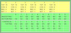
Pins are numbers by pin length. Pin number totals in each chamber must total 23. In our example, the highest cut between the change key and master key is '1'. The difference between cuts for the change key and master key is '4' (5-1 = 4). Therefore the total bottom pins loaded into the chamber would be '5' (4+1 = 5). The control key operates a second plug dia which is 10 numbers higher than the control key cut (10+3 = 13). Since we already have '5' loaded into the bottom chamber, an '8' pin is required to reach 13 (13-5 = 8). Finally, the total pin stack must equal 23. Since the temporary pin stack is 13 (8+5 = 13), the top pin must be a '10' (23-13=10).
A3 Charts
A3 systems were invented by Best Lock but they proved to be mechanically unpractical. Pinning rules are identical to the A2 system for pinning the bottom and change key cuts. In the example, the chamber would contain '5' (4 + 1). The control key operates a second plug dia which is 7 numbers higher than the control key cut (7+3 = 10). Since we already have '5' loaded into the bottom chamber, a '5' pin is required to reach 10 (10-5 = 5). Finally, the total pin stack must equal 16. Since the temporary pin stack is '10' (5+5 = 10), the top pin must be a '10' (16-10=6).
A4 Charts
A4 systems are also less popular today. However, a few companies such as Arrow &, Best do make A4 system available for additions to old A4 system already in existence. Rules are identical to the A2 system for pinning the bottom and change key cuts. In the example, the chamber would contain '5' (4 + 1). The control key operates a second plug dia which is 6numbers higher than the control key cut (6+3 = 9). Since we already have '5' loaded into the bottom chamber, a '4' pin is required to reach '9' (9-5 = 4). Finally, the total pin stack must equal 14. Since the temporary pin stack is '9' (5+4 = 9), the top pin must be a '5' (14-9=6).
Sargent 6300
For this example MK=661643, ck=803201, control key =667843.
Sargent LFIC cylinders only have a control key housing in spaces 3 & 4. In order to conserve change key cuts, spaces 1,2,5,6 normally have the same cuts on both the master key and control key. Pin stacks in spaces 1 & 2 add up to 15. Pin stacks in spaces 3 & 4 add up to 20. In the example, space one cuts are MK/Cont =6 and CK cuts =8. Therefore the temporary pin stack is (2+6 =8. The top pin is then '7'(15-8=7).
Spaces 3 & 4 use different dimensioning. In the example the temporary bottom stack is 8. "12" is an arbitrary number used by Sargent. Subtract the control key cut from 12 (12-7 = 5). In this example '5' is the control pin to use. The temporary pin stack now includes a '6' bottom pin, a '2' master pin and a '5 control pin. The total stack must be 20. Subtract the temporary stack (2+6+5) from 20 which equals '7' which becomes the top pin.
Corbin-Russwin
In 1970 Corbin and Russwin began new key dimensioning called System 70. System 70 uses depth increments of .028 and depths of 1-6. All key systems written before 1970 are called Pre70. Depending on the keyway, Corbin & Russwin generally used depth increments of .014 or .015 and depth numbering systems of 0-9 or 1-10. Key spacing did not change in 1970 so old pre70 systems can be converted to system70 systems as required.
Regardless of the C-R system,pinning rules remain the same except for the pin lengths required according to the key blank being used. Most of the variations used by C-R are listed here.
The control key operate spaces 2,3,4,5. Generally spaces 1 and 6 use the same cuts on the control key and the master key. In all C-R charts for this article the MK cuts are 111111, CK cuts are 555555 and control key cuts are 133331. Pinning for CK and MK are figured in the normal way. In this example the master key has the highest cut ('1') so that is the bottom pin. The CK cut is '5'. Subtract (5-1=4) to obtain the master pin. The temporary pin stack becomes '5' (4+1=5).
Corbin-Russwin uses plus and minus pins for control numbering. In this case the temporary bottom stack adds up to '5'. In space two the control key cut is a '3'. Subtract the temporary pin stack from the control key cut (3 - 5 = minus 2) to determine the control pin. Finally, the top pin is the same number as the control key cut. In this example it would be a '3'.
Each Corbin Russwin chart shows the various pin lengths used according to the keyway and vintage of the key system being serviced.
Schlage & Yale SFIC
Both Schlage and Yale use standard pinning systems without a control key core. Control keys will have longer key blades to operate a retaining system at the rear of the plug. Normally the control keys will contain the same key cuts as the master key in order to rotate to plug. A tip cut on the extended plug will operate the retainer for cylinder removal. In most cases Yale will have a '1' cut in the extended tip position and Schlage will have a '2' depth n the extended tip position.
Editor's Note: Please see the online version of this article at www.locksmithledger.com/12440229 for additional charts in different formats.
