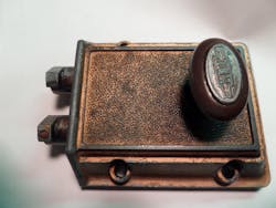
A subscriber contacted us recently and complained that it was impossible to find parts to repair older locksets. He was right and there is no simple answer. First, stamped steel parts have replaced the brass castings formerly used. Clean air regulations and higher cost of brass castings have doomed most old locks to extinction. Second, intricate designs and complex parts configuration found in older locks required hand-fitting. Mass production won out over hand fitting and the result is a world of discard and replace locks as they regularly malfunction.
A good example of an intricate lock is the Keil rim deadbolt (photo 1). Due to the large strike plate cutout, replacement with current lock designs is not a good choice. A locksmith called Locksmith Ledger and asked if we could provide assistance to repair a Keil lock and we agreed. Information stamped on the lock cover showed patent dates of 1917, 1922 and 1926. We have seen similar Keil locks which contained all brass castings. This lock used die-cast parts in place of brass (photo 2). It was probably made during the second world war when brass was a scarce commodity.
Basic parts in the lock functioned properly despite its age. Unfortunately the thumb turn was permanently fastened to the bolt works so individual parts could not be removed for inspection or cleaning. The real problem was a broken tension spring. Someone had tried to make a new spring by using paper clip material. Obviously the first time the lock was used the spring bent out of shape and became useless.
There are spring winders available on the market but it is almost as easy to wind most springs using only a suitable round shaft and a vise. Many sources of wire material can be found on the internet by typing "piano spring wire" on Google. .035" diameter piano wire was used for this repair job.
Begin by finding a scrap piece of round rod material which is the same diameter as the wire retaining stud in the lock. In this case a large nail had the correct diameter. Next, file a small notch crosswise on the nail. This provides a holding area for the piano wire as it is tightened in the vise. Extent one end of the piano wire past the notch in the nail to provide one working end for the new spring. Determine the winding direction for the spring and then tighten the nail and wire into the vise jaw with the filed notch as close as possible to the top of the vise jaw. Keep rotation of the wire as close as possible to each finished lower wire rotation and make as many spring rotations as required (photo 3).
The original Keil shape required extra bends at each end. One end must be bent to fit around a notched post. The working end must have a 'V' shape (photo 4). The part under spring pressure moves approximately one half inch and the 'V' spring shape maintains tension in the center of the moving part regardless of where that part is positioned. Photo 5 shows the new spring ready for 60 more years of work.
About the Author

