Passive security plays an important role in securing entryways by helping protect against unwanted entry. An intruder seeking to forcibly gain entry will, in most cases, choose to attack the entryway using tools such as lock picks, drills, pry bars, or blunt objects.
In October 2014 I wrote about the role of security strike plates in a passive security plan (Security Strike Plates: The Other Side of Door Hardware, www.locksmithledger.com/11658939) and this was followed up the role of latch protectors in January 2015 (Passive Security: Deterring Forcible Entry, www.locksmithledger.com/12025406.) I highly suggest revisiting these articles to find out more about passive security.
Additional passive security solutions available and this month I’d like to touch on the proper installation of mortise locks, as it relates to access control.
Mortise locks are incredibly durable, better constructed than a typical bored lock, and typically designed for heavy-duty use. The mortise lock rests in the interior of the door so that only a small portion of the hardware is actually exposed. The deadbolt of the mortise lock is integrated into the lock body, which makes the lock more secure. This adds a certain level of security into the overall security plan. The extra strength and durability of mortise locks are ideal for commercial use because the mortise locks can withstand higher cycle counts. Lastly, added functions can increase the security features of the entryway. All of these reasons make mortise locks the ideal choice for controlling access when they are properly and professionally installed.
The entryway is only as secure as the accuracy and precision of the preparation because proper preparation prevents poor performance. The overall security plan can easily be compromised when the entryway is not properly prepared to receive the door hardware. Taking out too much door material can lead to an improper hardware fit or even an expensive door replacement. There can also be negative consequences regarding re-labeling fire rated doors if the preparation is not done properly. This is in addition to any liability that could be occur if the contents of what the mortise lock is securing is compromised or if the entryway cannot withstand an event in which the door had been previously approved or certified.
It is important to note that the vast majority of door hardware installations occur to existing entryways in occupied buildings. Always refer to your local Authority Having Jurisdiction (AHJ), Life Safety Codes, and NFPA 80: Standard for Fire Doors and Other Opening Protectives when modifying an entryway, especially one with a fire rating.
For a bored to mortise conversion installation for an existing entryway, there are two aspects of the preparation process to focus on and two types of PRO-LOK installation tools to use:
- Tool 1: To prep the mortise body and faceplate (Item # INJIGC-MORT
- Tool 2: To prep the face of the door (INCL-PRO + IN51 + IN434-PRO)
Mortise Lock Body and Face Plate Preparation
- Align and attach PRO-LOK’s self-centering INJIGC-MORT: Mortise Jig to the wood door in the proper vertical position using the Top and Bottom Height Clamp and Stop so that the latch bolt of the lock will properly correspond with the new frame strike upon final installation. Height of 6-1/2” for the mortise pocket is common.
- Apply the INJIGC-MORT-CWB27, 1-1/16” diameter carbide tipped cutting bit, to the boring shaft, adjust the depth to the lock body, and tighten the depth collar to the depth of the lock body (See Photo 1). 4-9/16” depth of the mortise pocket is common. Note: Fire-rated doors must conform to ANSI A156.115 dimensions, width may not exceed 1-1/8”.
- Put on safety glasses and other protective equipment. Attach the power drill to the boring shaft and begin machining the mortise pocket, approximately ½” at a time, top-to-bottom, until full depth has been achieved. This will occur when the depth collar meets the aluminum housing. Remember to shave the wood, not plunge (See Photo 2).
- Clean the debris and sawdust from the mortise lock pocket.
- Change the cutting head on the boring shaft to the INJIGC-MORT-CWB32, 1-1/4” diameter carbide tipped cutting bit, and adjust the depth to the lock face plate of the mortise lock being installed. 7/32” depth is common. Tighten the depth collar for consistent depth during machining.
- Verify the vertical alignment and settings on the front of PRO-LOK’s INJIGC-MORT: Mortise Jig to be sure it’s correct to create the 1-1/4”x 8” face cutout at the proper location.
- Put on safety glasses and other protective equipment. Attach the power drill to the boring shaft and gradually machine the face plate in the same manner as the mortise pocket.
- Remove the INJIGC-MORT Mortise Jig from the door and completely clean all sawdust and debris from the mortise pocket.
- Using a straight chisel or cornering chisel, square off the corners of the lock front. The mortise pocket preparation is now complete and steps 3 through 9 should take less than 5 minutes combined (See Photo 3).
Inside and Outside Door Preparation
PRO-LOK’s Professional Installation Template Series is specifically engineered to prep both the inside and outside of the door in one simple-to-use fixture and designed to cut the hardware installation time to a fraction of the traditional method of using paper templates and freehand drilling. This modular template system provides a more accurate and efficient installation because it not only maintains full and direct contact with the door, but also uses true sized holes (many holes in PRO-LOK’s templates are equipped with hardened, heat treated bushing). These two unique features help reduce installation errors and ensure accuracy. The accuracy enjoyed by using this system will save time spent mounting the hardware and eliminating “call-backs” will make for satisfied customers. The time savings can provide the opportunity to make more money by freeing up time to capture more business.
All installation templates are designed to work with the INCL-PRO Professional Series Universal Clamp and are milled from ½” solid aluminum with a black anodized finish. The concept is a modular one; once the INCL-PRO clamp has been purchased, additional templates can be purchased at any time as needed, and use the same clamp. This system makes for fewer tools at a more economical price.
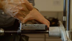
- Inspect the mortise pocket and insert PRO-LOK’s IN51: Mortise Alignment Centering Tool into the pocket to prepare for the INCL-PRO and face templates. The IN51 is used to locate the face templates correctly relative to the mortise body to ensure proper alignment (See Photo 4).
- Attach the INCL-PRO to the appropriate hardware specific templates for the hand of the door and specific model lock being installed. In this circumstance we will be using PRO-LOK’s IN434-PRO and installing the Sargent Passport PG hardware. The hardware-specific templates attach to the INCL-PRO with three heavy-duty Allen screws on each side.
- Attach the installation jig, consisting of the Professional Series Universal Clamp (INCL-PRO) and hardware specific installation templates (IN434-PRO), onto the door and use the Mortise Alignment Centering Tool (IN51) for alignment. Follow the clamping instructions that come with the INCL-PRO (See Photo 5).
- Use twist bits, smooth bore hole saws, or plunge router, as appropriate, to create the surface holes for the operational elements required for the particular lock function being installed (See Photo 6).
- Apply the top plate attachment and finish drilling the small round surface holes. The purpose of the top plate is to give the installer accurate true sized holes with hardened, heat treated bushing for all of the holes associated with the lever and through bolts.
- Complete the hardware prep of the rectangular card reader using a plunge router and the collar that PRO-LOK included with the template. The cutting tool surface should not come in contact with the installation templates.
- Loosen the clamping knobs and remove the installation jig from the door.
- Install the lock using the manufacturer supplied fasteners and accessories. Use PRO-LOK’s flat plates or wrap plates to go between the door and the hardware to cover up any retrofit holes not in use, while giving access to the holes needed. (See Photos 7 and 8).
Successful installations and achieving the desired result comes from proper preparation. Being properly prepared and using the correct tools increases your chances for success, repeat business, and satisfied customers. Most importantly, proper preparation helps to ensure the integrity and continuity of the overall security plan.


