Concealed Vertical Rod (CVR) exit devices operate by the push pad or bar moving in towards the door to simultaneously release the top and bottom latches within the body of the door from the strikes. The head (case) controls the vertical movement. Once the latches are no longer confined by the strike, continued pushing on the device opens the door. Latching mechanisms can vary by manufacturer and model. Some top and bottom latches are part of a single unit with the rods connected to an inner chassis; others are two separate actuator mechanisms.
Properly functioning CVR exit device vertical rods move freely within the door. As the door is closing, the bottom latch does not drag on the floor. The top latch does not scrape against the strike plate as the door enters the jamb. When the door is closed and the trip mechanism is contacted, the latches are secured in place, engaging the top and bottom strikes. The latch engagement is sufficient to stop eiter the top or bottom of the door from moving away from the strike.
Concealed vertical rod exit devices provide a clean installation. Architects love them since only the device (or push bar) is mounted onto or into the surface of the door. Healthcare facilities love them because concealed rods eliminate the possibility of carts, gurneys, wheelchairs and hand trucks hitting exposed rods and latches that can affect the operation of surface vertical rod exit devices.
CVR exit devices provide top and bottom (two-point) latching. For many double door applications, this eliminates the need for a mullion.
That's the good news. The bad news for many concealed vertical rod exit devices is they have difficulty staying in adjustment. To make matters worse, adjustment often requires the bottom rod latch to be exposed. Because of the limited amount of room beneath the bottom of the door and the floor, lowering the door is often required. When CVR exit device rod and case assembly is one unit, you need approximately four feet above the door in order to remove the rod assembly for service. Many buildings do not have sufficient ceiling height to enable this operation. As a result, lowering the door is often required.
Concealed vertical rod exit devices have greater difficulty staying in adjustment and there is less range within the adjustment. The problem is if either latch goes out of adjustment, the door is no longer secure. The alignment must be checked and the problem resolved.
To help resolve exit device adjustment problems, Command Access Technologies developed the "Push to Set" (PTS) electronic travel adjustment for latch pull back-equipped exit devices including concealed vertical rod style. PTS technology simplifies latch positioning adjustment. The adjustment is accomplished without having to remove anything from the door or gain access to the top and bottom latches. "Push to Set" latch pull back mechanisms also work with top rod- only concealed vertical rod exit devices.
For this article, I was invited to the replacement of two concealed vertical rod exit devices on an exterior wide stile aluminum glass double door opening at the Command Access headquarters. They decided to install their PD25/26 concealed vertical rod exit devices, providing remote release on the right hand outswing door. On this door, a Command Access Technologies PD25 Concealed Vertical Rod Exit Device with "Push to Set", motorized electric latch retraction was installed. On the left hand door, a Command Access Technologies PD26 Concealed Vertical Rod Exit Device was installed. A wireless remote release was installed to remotely provide access.
The items installed onto this outswinging double aluminum glass door are the PD26-CVR, PD25-M-CVR, door loop, remote release and power supply.
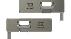
The PD26-CVR is a concealed vertical rod exit device that meets ANSI A156.3 Grade 1 requirements. This fire or panic rated, field-reversible exit device has a free wheeling clutch mechanism. The PD26 accommodates aluminum glass storefront doors with a minimum stile width of 4-1/2". CVR models have a top and bottom travel of 7/16". The projection is adjustable up to one inch to accommodate opening variations. The PD26-CVR is designed to accommodate door sizes from 32" to 36".
The PD25-M-CVR concealed vertical rod exit device is equipped with Motorized Latch Pullback (MLP). Voltage range for this electrified exit device is 22 to 30 VDC. System protection shuts off the unit when voltage exceeds 30. The MLP has a 1A peak current draw and 125mA current hold. The current hold provides electric dogging by retracting the push pad, placing the door in passage mode.
To remotely unlock the electrified exit device, an RF-433 MHz radio controlled transmitter with receiver was installed. This digital system uses rolling code technology providing additional protection. The transmitters are available with one to four buttons wireless and one button 3-volt and 9-volt hardwired. The red LED on the transmitter confirms transmission, battery life and provides troubleshooting assistance. Each transmitter can be programmed to an unlimited number of receivers. Up to 100 transmitters can be programmed to a single receiver.
To transfer the power from the jamb to the door stile, a Command Access Door Loop part number DL-20D (duronatic finish) with a field sizeable 20-inch cable was installed.
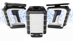
To power the motorized latch pullback, the decision was made to use the Command Access PS1 filtered and regulated 24VDC high surge current power supply. This single input/output, solid-state power supply provides high current in-rush for a single exit device. The output voltage is 24-27.5VDC regulated at one Amp. The power supply is installed into a 10" by 10" by 4" metal enclosure.
The PS1 power supply’s design can simultaneously energize two latch pullback exit devices. Its adjustable voltage allows for centralized power supply installations with long wire runs. The PS1’s large capacitor provides smooth delivery of power for motorized devices with ample stored power to handle high use applications.
To simplify the installation, both doors were lowered and the exit devices were installed. A locating block was installed in the bottom rail to provide more secure mounting brackets for the bottom latch. Another advantage of "work bench installation" was the rod length adjustments could be made much easier.
Once the existing exit devices were removed, and the PD25-M-CVR and PD26-CVR exit devices were installed and wired, the final steps were to check the adjustments and do the operational testing.
The concealed vertical rod exit devices were tested and mechanically operated as designed. Then the motorized latch pullback was powered. The CVR exit device push pad was pressed to the release position (almost completely pressed). The device was powered. Pressure continued to be exerted to keep pad depressed. The motorized latch pullback beeped 6 times. After the beeps stopped, the push pad was released. The exit device was in adjustment. The top and bottom latches retracted when the remote fob was pressed, permitting the door to be swung open from the exterior.
The adjustment position in relation to the position of the push pad can be changed by varying the amount of pressure exerted against the push pad. The adjustment can be repeated until it meets approval.
The "Push to Set " feature is available on all Command Access Technology's motorized latch-pullback exit devices.
For more information, contact your local locksmith distributor or Command Access Technology, Telephone: 888-622-2377. Web Site: www.CommandAccess.com