In part one of the Security Door Controls (SDC) IP Pro article, we discussed Local Area Networks (LAN), Power over Ethernet (PoE) and the browser-based, software embedded SDC IP Pro Controller. (Read part 1 at www.locksmithledger.com/12015903.) This type of network access control system requires a Category 5e or 6 Ethernet Cable to carry both data and power. The IP Pro Controller and SDC PoE-capable products can be used to build a single door access control system.
For this article, we will do a dry run of the IP Pro component-based electronic access control system. We will connect all of the components, power, and will do basic programming without actually installing the access control system into an opening. Instead, we will be laying them out on a tabletop. This type of dry run is recommended before installing the components to ensure proper operation and prior programming to save time.
Components used to set up the system are the SDC IPRW Weigand Proximity Card Reader, Electra Pro Z7252EQ Electrified Cylindrical Lock and IP Pro Single-Door Access Controller Starter Kit, which includes the active Injector and Splitter.
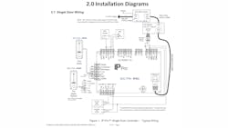
When wiring this system’s components for short wire runs, use 18-2 stranded from the controller to power the lock, and 24 gauge stranded for reader, door contact and REX. When using the REX and door contact, an additional two wires each is required. Where permissible by code or the Local Authority Having Jurisdiction (LAHJ), in lieu of the REX, a second card reader may be added for exit accountability. The IPRW Reader requires a minimum of six conductors. They are connected to the three-part connector on the left side of the Controller board. The connections are:
- Green lead to Data 1
- Blue lead to Data 0
- Red lead to +12V
- Black and white leads to 0V
- Brown lead to Red
- Yellow lead to Green
The Orange lead is not used for this installation.
To provide the PoE, the Injector requires 120VAC input. The Injector is powered directly by inserting the provided power cord into an available 120VAC receptacle, injecting power into the Ethernet cable and providing PoE+ power to the splitter. The splitter splits off the power from the Ethernet Cable to a positive and negative terminal. The output of the provided splitter is up to two Amps at 12VDC. The Cat 5e or 6 Ethernet cable connects to the Ethernet connector near the right side bottom corner on the controller circuit board.
The splitter receives 12VDC directly from the controller. The controller provides power for the credential reader. For this configuration, power requirements for the lock, reader and Controller are approximately 900mA. Installers should determine the optimal wire gauge versus the distance from the splitter to the controller and the lock.
For this installation, the wiring from the “+” and “-“ splitter terminals connects to the "+12V" ("+") and the "0V" ("-") terminals at the top right side of the controller circuit board. Also, the "+" lead from the splitter terminal connects to the "C" Main Relay terminal at the bottom left to power the electrified locked. A wire is run from the "NO" terminal to the fail secure lock and from the negative lead of the Splitter run to the lock. See drawing of circuit board for details.
When wiring an electronic access control system, it is extremely important to observe polarity (positive and negative). For this system, be sure to observe polarity when wiring the power leads from the splitter to the Controller. Use red and black wires to ensure that anyone servicing the system will know red is positive and black is negative.
For the purpose of this article, we will use a laptop computer to program and administrate our single-door access control system. The laptop is wirelessly connected to the Internet. A Cat 5e Ethernet Cable is connected from the laptop to the injector. The maximum Ethernet Cable run is 100 meters (~ 328 feet).
Once the system has been configured, power the laptop and the injector. With the controller cover open, the circuit board status indicators can easily be seen. When they are blue, the controller has power and communications. Because we have the cover open on the controller, the fault indicator illuminates red. The tamper alarm does not affect configuring the controller.
The first step is to configure the computer with a static IP address, default Subnet Mask (255.255.255.0) and Gateway (192.168.1.1). This enables the laptop to communicate with the IP Pro Controller using a standard Internet browser. For this article, the laptop will be assigned the Static IP Address 192.168.1.100. The Static IP address is fixed at 192.168.1. We choose the final value, which can be 3-255. Because the controller is 192.168.1.160, the 160 cannot be used as part of the Static IP address.
Once the laptop has been configured, using the Internet browser, connect to the controller by entering the default address “http://192.168.1.60“. The system will prompt for authentication credentials.
The IP Pro controller has two different default log-in credentials, Installer and User. The Installer credential is for configuring initial global communications and door settings. The User credential is for configuring day-to-day system management including adding, deleting and controlling access.
To begin configuring the IP Pro, log in under the Installer Credential. See the IP Pro manual for the default password. The manual is included with the controller or may be downloaded from the SDC website, www.sdcsecurity.com.
The IP Pro Manual contains systematic instructions, screen shots and charts with terminology and descriptions to guide you through the programming. If you are installing the system to operate within an existing network, you will now be able to change the Static IP Address of the controller to one that is assigned by the Information Technology (IT) department to enable the access control system to communicate properly within their network.
Once logged in using the Installer Credential, make certain Door 1 is enabled. Door 1 must always be the IP Door Controller. Once enabled, the Door Name Field can be changed to indicate the actual door name, location, etc., using a maximum of 16 characters. At this time, you can also program additional door settings. Door settings can be programmed whenever necessary to accommodate the Users.
To enhance security and prevent unauthorized personnel from accessing the system settings and changing programming, be sure to to change the log in password from the system default. Note: Always write down the password before programming. Make sure you indicate which letters are capitalized. Program the log-in passwords exactly as they are written down. Log out of the system when finished.
To program access, log in as the User. See the IP Pro manual for the default password. The User log-in determines the authorized User Codes, sets date & time, and assigns access rights.
From the User Home Menu, you can add individual users, add a batch of cards and show all users. For this article, we will be using Proximity Cards, which can have a 3-digit facility code and a 5-digit card number.
Begin the process by programming the first User. We will program a single Proximity Card for User 1. The IP Pro accommodates batch programming to simplify adding a large number of cards in sequential order. To batch program, make sure all of the cards have the same 3-digit facility code and are in numerical order. Begin with the card that has the lowest 5-digit card number as the Start User.
Users are programmed for single or dual credentials. They are automatically programmed into the User “Group 1", which by default is 24/7 access to all doors. It is important to save the information once the cards have been assigned.
Complete the initial set-up by adding User name information, Time & Date, Timezones, Holidays, Door Groups and User Groups. All of the User programming is completed through the eight menu choices on the left column. For example, within the Settings menu, there are tabs for Holidays, Add Holiday, Password, Date and Time, And Language. Complete the programming dedicated for the application. This single-door access control system is now operational.
Beyond the basics, the SDC IP Pro controller can be configured for advanced security features including anti-tailgating and anti-passback to restrict unauthorized individuals from gaining access. The controller can be configured to release any locked doors designated as fire exit doors when the fire alarm activates.
In addition to providing access, the SDC IP Pro offers door relay varying length timer configurations for the physically challenged and the elderly. The standard relay time is set in response to a valid card or the REX. For Users who require additional time to gain access, programming an Extend Relay option activates the door relay keeping the door open for additional time when they present their credential.
The IP Pro has single-door expansion boards for multiple door access control systems up to 32 doors using a single controller. The built-in browser based software allows for complete configuration of the IP Pro controller and all expansion door stations.
The IP Pro uses PoE to lower cost and simplify installation. SDC offers a range of products to complete an electronic access control system for one door with expansion capabilities for multiple doors. Using the IP Pro and Security Door Control readers, electrified locks and accessories provide a single source electronic access control system solution.
For more information, contact your local locksmith distributor or Security Door Controls, 801 Avenida Acaso, Camarillo, CA 93012 .Telephone: 805-494-0622. Web Site: www.sdcsecurity.com.


