The first installment of our commercial double door installation article discussed the use of a half-surface aluminum continuous hinge to position the doors within the opening, ensuring the gap between the two doors was correct. The door hardware was installed as designed and the doors operated smoothly. The new Norton CloserPlus Ram Hold Open Arm incorporates a patented ramp and plunger design that makes it easier to place the door in the open position.
In Part 2, we will complete the installation of the two Norton 8000 Series Door Closers, Design Hardware KRM Key Removable Mullion and two Sargent 80 Series Rim Exit Devices incorporating the Sargent Anti-Vandal Handle.
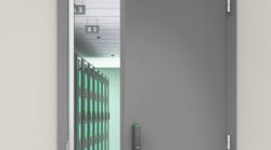
Hardware was installed on a non-fire rated secondary entry into an office building. The 5’8” opening was configured with two equal sized doors. After years of use and abuse, the doors were no longer in operating condition.
The replacement hollow metal doors are different widths, a 3'8" wide leaf and a 1'11" wide leaf. This configuration provides an oversized main entry door for deliveries. A removable mullion and two rim exit devices were selected instead of one vertical rod exit device and one rim exit device. This configuration provides the added benefit of less maintenance and improved security. For this installation, a single door and a sidelite were not an option. The company policy is to maintain the full opening, as you never know when there is an object that will require it.
On the exterior of the doors, only the IC rim housing within the anti-vandal handle was exposed. No handle was installed onto the smaller door. Schlage Large Format Interchangeable Core Rim Housing was installed into the anti-vandal handle to operate the larger door exit device.
Editor’s Note: Read Replacement Double Doors Secure Office Building, Part 1, online at www.locksmithledger.com/11365384 or in our May 2014 issue, pages 24-32.
Norton 8000 Series Door Closers
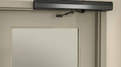
To close and latch the door, two Norton 8000 Series Door Closers with the CloserPlus Ramp™ (CLP-R) Arms were installed. These non-handed rack-and-pinion, cast aluminum body, heavy duty door closers have adjustable spring sizes of 1 though 6 with separate latch, sweep and backcheck valves. Standard arm applications allow for up to 180-degree swing.
Note: Always write the installation date onto closer body or cover. Keep the receipt. The Norton 8000 Series Door Closer has a limited 25-year warranty.
The door closers were mounted onto the push side of the door opposite the hinge using the parallel arm installation. The smaller door installation required some modification because of its width, making certain the arm did not contact the mullion and repositioning the alarm contacts, mounted beneath the header. The large door closer was first installed using the provided self-drilling screws into the door closer reinforcement. Pilot holes were first drilled. Once the mullion top retainer was located, the smaller door's closer was installed, somewhat modifying the installation dimensions to accommodate sufficient clearance for the arm.
Design Hardware Mullion
The Design Hardware KRM Key Removable Mullion was the next product to install. First, a mullion was installed onto an outswinging set of double doors. For this installation, the head cap and the outer dimensions of the bottom retainer were located against the interior face of the door when in the closed position. This ensured the door would close completely.
The mullion provided a solid stop for the doors. The mullion tube can be used to locate rim exit device strikes. This configuration provides a high level of security when using exit devices. Because of varying door heights, the mullion tube will normally be cut in order to accommodate the height of the opening.
The threshold was temporarily removed in order to install the bottom retainer directly onto the concrete floor using provided screws and expansion anchors. An opening had to be cut out of the threshold to accommodate the bottom retainer. In addition, a couple of mounting screws could no longer be tightened. Holes were drilled into the concrete and anchors were installed for the bottom retainer. The base of the bottom retainer was coated with silicone sealant for a strong seal.
Before reinstalling the threshold, it was cleaned and two lines of adhesive were spread on the underside to hold the threshold in place for many years. Mounting holes were enlarged using concrete drill bits and anchors were installed. The top retainer was installed into the header with the open end facing out. The opening was measured to determine the length needed for the mullion.
The mullion headcap assembly was placed onto the tube to determine the overall length. The opening between the top and the bottom retainers was measured. This length was subtracted from the overall mullion length. The mullion tube was cut to size from the end that slides into the headcap.
Important: Do not cut the end of the mullion that has the warning label.
The IC mortise housing and the back plate were installed into the headcap chassis assembly. The headcap was installed onto the mullion tube. A mallet and a wood block were used to make sure the headcap was properly seated. Two 11/32" diameter holes were drilled through the tube using the headcap openings. Two 13/32" diameter holes were drilled through the side opposite the IC mortise housing. Thru bolts were installed from this side. Two ¼-20 security screws were inserted and tightened using a 5/32" security hex wrench. The mortise cylinder was installed into the headcap and tested to be certain the mechanism would unlock.
To mount the mullion onto the bottom and top retainers, the bottom end of the mullion tube was slid over the bottom retainer with the opening in the headcap towards the top retainer. With the mullion slid onto the bottom retainer, it was tilted up so the headcap could be slid over the top retainer. The mullion was latched in place, fixed against the top retainer.
The mullion should not move back and forth. If the mullion moves, remove the mullion and extend the setscrew located along the rear of the top retainer. Once the setscrew has been properly adjusted, install the mullion. An exposed setscrew along the side of the bottom retainer was tightened, once the mullion was in place, making the bottom of the mullion rigid. This setscrew must be loosened prior to removing the mullion from the opening. Once the setscrew has been loosened, the key was inserted into the mortise cylinder and rotated to release the locking mechanism. The mullion was carefully pulled away from the top retainer.
Sargent 80 Series Rim Exit Devices
Next to be installed were two Sargent 80 Series Rim Exit Devices and the Sargent Anti-Vandal Handle using Schlage Large Format Interchangeable Core Rim Housing. The rim cylinder cross bore holes were factory drilled.
To accommodate code, the rim exit device centerline was located 41" above the finished floor. Four thru holes had to be cross-bored in the larger door to install the anti-vandal handle. Both rail assemblies had to be shortened, as the openings were not standard width. The 1'11" door is probably the smallest width that a Sargent 80 Series exit device can accommodate.
The larger door exit device was installed first, using a torpedo level to ensure the push rail assembly was level. Two Sargent 649 strikes were installed onto the sides of the mullion tube to accommodate the two exit devices latching mechanisms. Then the smaller door exit device was installed to verify that both exit devices were at the same height. No external trim was installed on the smaller door.
Norton 8000 Series Door Closers
With the door hardware installed, the next step was to adjust the door closers for power, backcheck, sweep and latching. Once adjusted, the doors were checked to be certain they were opening, closing and latching. When adjusted, the covers were installed. Norton 8000 Series door closer covers have two holes on the ends to accommodate adjustments to the sweep and latch, eliminating the need to remove the cover.
Providing the total solution including the installation of the doors, continuous hinges, door closers, mullion and exit devices with trim gives your customer many years of operational life, peace of mind during those years and the reason to hire a professional locksmith to make sure their openings are operational, safe and secure.
Correction: In the first installment of this article, the door closer model was misidentified. It is a Norton 8000 Series, not the 7500 Series.
For More Information
For more information on products discussed in this article, contact your local locksmith distributor or the following manufacturers:
Design Hardware: www.designhardware.net
Door Components: www.doorcomponents.com
Norton Door Controls: www.nortondoorcontrols.com
Pemko: www.pemko.com
Sargent Lock: ww.sargentlock.com
Schlage Lock: www.allegion.com