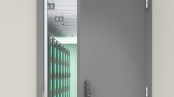
I was invited to observe the installation of new double doors, rim mounted exit devices, an anti-vandal handle, a removable mullion and surface-mount door closers on a non-fire rated secondary entry into an office building. The 5’8” opening was configured with two equal sized doors. After years of use and abuse, the doors were no longer in operating condition.
The replacement hollow metal doors are different widths, a 3'8" wide leaf and a 1'11" wide leaf. This configuration provides an oversized main entry door for deliveries. A removable mullion and two rim exit devices were selected instead of one vertical rod exit device and one rim exit device. This configuration provides the added benefit of less maintenance and improved security. For this installation, a single door and a sidelite was not an option. The company policy is to maintain the full opening, as you never know when there is an object that will require it.
Examining the opening provided some interesting information. Not only were the jambs concrete filled, but they were also tweaked and out of plumb. Installing doors into this opening using butt hinges would not be practical if appearance and having a good seal was important. To ensure the doors would look nice and operate properly, a decision was made to install heavy duty, half-surface continuous geared hinges.
Installing doors using half-surface continuous hinges gives locksmiths the ability to compensate for sub-par construction, and building settling and aging issues. Half- surface continuous hinges are designed mainly for retrofit work because this type of continuous hinge provides the ability to adjust both side-to-side and front-to-back. This is possible because the half-surface continuous hinge has two different leaf configurations. The concealed leaf that mounts onto the frame rabbet in front of or behind the soffit, depending upon if the door is outswing or inswing. This leaf can be positioned in order to have the door plumb within the opening even if the frame is not. The exposed face of the door is surface mounted onto the rear of the surface leaf can be positioned to fit the opening even if the opening is not square to the frame.
For security purposes, the main door will be equipped with an anti-vandal handle on the exterior. Only a rim cylinder will be mounted into the handle. The rim cylinder will retract the rim exit device latchbolt. No exterior trim will be mounted onto the smaller door.
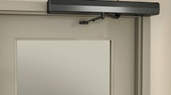
To keep the doors closed, two surface-mount door closers will be installed onto the interior (protected) side of the door. The closers will be equipped with newly introduced hold open arms designed to limit the amount of wear and tear on the closer and hinges.
A keyed removable mullion is a stop located within the opening that changes the operation of the two doors from interdependent into single operation doors. The mullion tube provides a mounting location for each strike to accommodate the rim exit devices. It also prevents over swinging of the doors.
The keyed mullion can be removed to provide a five-foot plus clear opening. The mullion is mounted by placing the tube onto the bottom retainer and swinging the headcap assembly into the top retainer. The mullion is swung into position from the exterior towards the interior of the building, stopping it from being slid out of position when the doors are closed and latched. A key is required to remove the mullion. No key is required to attach the mullion.
Door Hardware List
Our list of door and door hardware companies include:
1.Door Components Honeycomb Core 16 Gauge Doors whose vertical edges are continuously welded, providing a seamless appearance. There is hardware reinforcement for the exit device and the door closer.
2.Design Hardware KRM Key Removable Mullion is non-fire rated and operates using a 1-1/8" or 1-1/4" length mortise cylinder. The 2" wide by 3" deep mullion steel tube comes with the separate headcap assembly.
3.Norton 8000 Series Door Closers with the CloserPlus Ramp™ Arms provide the closing force. This new, patent pending heavy duty arm uses a ramp and plunger hold open design and has a dead stop to ensure the door swing does not continue when at the hold open position.
4.Pemko Grade 1 Heavy Duty Half Surface Continuous Geared Hinge. This clear anodized aluminum continuous hinge has bearing centers every three inches.
5.Sargent Anti-Vandal Handle with cylinder opening and no protective lip. This handed, 12- gauge stainless steel trim is through-bolted. The matte plastic coated grip handle is ADA compliant.
6.Sargent 80 Series Rim Exit Devices are ANSI A156.3 Grade 1. These standard wide stile design exit devices are non-handed. The shorter exit rail has been cut down to accommodate the opening.
Installation
The installation began by removing the pins from the three butt hinges per door. Before removing the pins, the setscrews securing the pins had to be removed. Once the pins had been removed, the doors were lifted off the hinges. The leaves were still onto the door edges and the frame soffits. A battery operated reciprocating saw with bi-metal blade was used to cut off the knuckle portion of the hinges that extended beyond the edge of the doors and the soffits.
A battery operated grinder removed and smoothed the excess leaf material. Make sure the hinges on the soffits are securely attached. These hinge remains filled the hinge openings in the soffit and the new doors, as the half-surface continuous hinges would not. The hinge remains were removed from the old doors and installed onto the new doors. Silicone sealant was used to seal the areas between the hinges and cutouts in the soffits and door edges.
The next step was to remove the alarm contacts from the doors. They were kept out of the way until the installation of the doors had been completed, and then they were re-installed.
Measurements were taken to determine the length of the Pemko heavy duty half-surface aluminum continuous geared hinges. For this opening, 83" continuous hinges were ordered. This Pemko continuous hinge can be cut in the field.
Important: Hinges should be cut by removing material from the bottom. Cutting a continuous hinge, makes the hinge handed and should never be installed with the cut side up.
The length determined included positioning a 1/8" diameter drill bit between the header and the each continuous hinge and sufficient space above the threshold. The drill bit was positioned at the front or rear edge of the soffit depending how out of plumb was the jamb. A gap of approximately 3/8" was left between the bottom of the continuous hinge and the threshold.
A six foot level was placed against each side of the opening to see the overall condition of the frame. Each door was then placed into the opening to understand the degree of tweaking required.
When the level was positioned plumb within the opening, this determined where the Pemko Grade 1 Heavy Duty Half-Surface Continuous Geared Hinges would have to be positioned. The continuous hinge was placed into the opening at the location. In this position, the continuous hinge was just about plumb. Three vertical screw holes from the top, with one screw in the middle and one at the bottom, were installed.
There are three double holes at the top. If the hinge needs to be adjusted, the adjacent screw can be used to install the first screw. Once tight, the second hole can be reformed to install the other mounting screw. Because the jamb was concrete filled, each mounting hole was drilled starting with a pilot hole, the correct diameter drill bit, concrete bit and the tap to thread the opening.
Note: When installing doors using aluminum continuous hinges, the doors will settle approximately 1/32" to 1/16" as a result of compressing the bearings.
This temporary mounting permitted the Door Components Honeycomb Core 16 Gauge Doors to be placed within the opening and the surface leaves placed against the face of the doors to ensure they were plumb. After a bit of adjusting the concealed leaf mounting screws positions, the doors were plumb within the opening. The remaining concealed leaf continuous hinge mounting screws were installed for both doors.
The next step was to position the smaller door within the opening and against the half surface leaf. The smaller door was spaced up from the bottom, down from the top and parallel to the larger door. For our installation, the gap between the header and the top of the door should be 1/8" + 1/16". The gap between the bottom of the door and the top of threshold should be no more than 3/8". The gap between the two doors should be 1/8" + 1/16". Shims, screwdrivers, hex wrenches, putty knives or wood chisels may be used to position the doors. Be careful not to damage the primered surface of the door.
When the closed doors were within the above gap tolerances, the door faces aligned with each other at the top and the bottom, and the half surface leaves were flush against the doors. The doors were at the same height within the opening. We marked the locations for the mounting screws on the small door face. Being careful not to move the larger door, three mounting screws were installed through the half-surface continuous hinges and into the doors: one at the top, middle and bottom. Shimming materials were removed from the smaller door.
Next, operation was tested. The smaller door should have the proper size gaps and should swing smoothly to open and close. The smaller door was installed first because it is easier to position within the opening. Once the smaller door was properly positioned, the remaining mounting screws were installed.
With the smaller door in position, final adjustments were made to the larger door within the opening. When the two door faces were close to and square with the gap at 1/8" + 1/16", the top, middle and bottom mounting screws were installed. It should not take more than approximately one pound of force to open or close the door if it is in adjustment.
Next we checked to see if the two doors are plumb, the faces aligning with each other at the top, middle and bottom. If not, the concealed hinges were adjusted in or out at the top or bottom to be in alignment. Once the continuous hinges were adjusted, remaining mounting screws for both leaves were installed, as were the through bolts for the half-surface leaves.
We finished the aluminum continuous hinge installation by cutting the cover plate to size and installed it using a wood block and a mallet. The cover plate should only be installed after the mounting screws and bolts in the half surface leaves have been installed and final door operation has been tested.
At this time, the alarm switches for the two doors were reinstalled.
In the second half of this article, we will continue with the installation of the two Norton 8000 Series Door Closers with the CloserPlus Ramp™ (CLP-R) Arms, the Design Hardware KRM Key Removable Mullion and the two Sargent 80 Series Rim Exit Devices and the Sargent Anti-Vandal Handle.
For More Information
For more information on products discussed in this article, contact your local locksmith distributor or the following companies:
- Design Hardware: www.designhardware.net
- Door Components: www.doorcomponents.com
- Norton Door Controls: www.nortondoorcontrols.com
- Pemko: www.pemko.com
- Sargent Lock: www.sargentlock.com