KABA explains the primary purpose of high security locks as "the prevention of unauthorized key duplication." High Security locks first appeared in approximately 1970. High security lock designs usually contain some kind of secondary locking feature which separates them from standard bottom pin/top pin locking systems. As the popularity of high security locking systems grew, so did the amount of lock companies who offered their own versions.
Another feature of high security locks was that lock cylinders were made to interchange with existing lock bodies. This provided an economical way for building owners to convert to high security key systems without having to replace existing lock hardware. Adding a new high security lock cylinder was the only modification necessary.
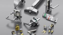
High security cylinder versions were originally available to retrofit mortise, rim and key-in-knob cylinders. Many large building complexes used interchangeable core (IC) lock systems so high security IC cylinders also became available from almost every lock company.
One of the most popular High Security lock cylinders is Kaba Peaks. Variations between each change key are accomplished with a standard bottom pin/top pin system. A secondary locking system consists of an additional pin located near the face of the plug. Key blanks require an extended peak section in order to lift this additional pin to the shearline, and this is probably where 'Peaks' got its name.
An important consideration for any high security locking system is the length of its patent life. When a patent expires, other companies can possibly make previously restricted key blanks available and key control is diminished. Kaba has maintained patent life by continually adding new, patented features to assure dependable key control and to avoid any possible infringements.
Original Kaba Peaks cylinders were called Classic. Preferred and Global lock systems have followed. While additional patented features have been added to Preferred and Global products, formulas used for pinning top and bottom pins remain the same. Kaba Peaks lock cylinders are available to fit almost every OEM cylinder shape such as SFIC or LFIC housings, key-in-knob locks, cylindrical deadbolts plus replacements for standard 1 1/4" diameter mortise and rim cylinders.
Kaba Peaks lock cylinders are designed for use with either standard A2 or A4 depth increments. Depending on the lock systems being replaced, Kaba Peaks cylinders may be available with cut-to-cut spacing of either .140 or .150. When all of these variations are taken into consideration, pinning mathematics can vary considerably depending on the type of Kaba Peaks cylinder, cut-to-cut spacing and the A2 or A4 depth increments being used.
Original Peaks bottom pins are .003 shorter than aftermarket replacement pins and are crowned for smooth operation. Some original Peaks bottom pins are spool-shaped for added security. According to Kaba Peaks, non-original pins will not work properly in Kaba products and their use voids product warranty.
Locksmiths who are familiar with pinning standard SFIC cores know that an A2 pin stack should add up to 23 and an A4 pin stack should add up to 14. These numbers never change since SFIC cores all have the same plug diameter and housing dimensions.
Kaba Peaks cylinders are available in a variety of cylinder sizes which results in six arrangements of pin sizes and stack totals for A2 systems and six arrangements of pin sizes and stack totals for A4 systems.
- Kaba A2 bottom pins are listed as: 0A-9A & 0J-9J.
- Top pins for A2 systems are listed as: 2B-19B.
- Kaba A4 bottom pin are listed as: 0E-5E & 0K-5K.
- Top pins for A4 systems are listed as: 1F-11F.
Dual sets of bottom pins are required to compensate for larger or smaller plug diameters. In some instances top pins longer than 11F or 19B may be required to complete a pin stack. In those cases, use two top pins to build the stack. Example: Add both an 11B pin and a 12B pin to the pin stack when a 23B length pin is required.
Peaks Interchangeable core cylinder plugs are retained with a 'C' clip. This allows the plug to be removed during rekeying instead of removing the top caps. A special follower is available from Kaba-Ilco to facilitate both rekeying and the installation of the Peaks pin.
Cylinder pin stack requirements:
A2 SYSTEMS
Key-in-knob (std plug dia)
A bottom pins / B top pins / pin stack = 26
Key-in-knob (lrg plug dia)
J bottom pins / B top pins / pin stack = 26
Conventional Mortise/Rim Cyl
A bottom pins / B top pins / pin stack = 31
SFIC IC Core
A bottom pins / B top pins / pin stack = 23
C-R LFIC IC core
J bottom pins / B top pins / pin stack = 26
Yale & Medeco LFIC
A bottom pins / b top pins / pin stack = 26
A4 SYSTEMS
Key-in-knob (std plug dia)
E bottom pins / F top pins / pin stack = 15
Key-in-knob (lrg plug dia)
K bottom pins / F top pins / pin stack = 15
Conventional Mortise/Rim Cyl
E bottom pins / F top pins / pin stack = 18
SFIC IC Core
E bottom pins / F top pins / pin stack = 14
C-R LFIC IC core
K bottom pins / F top pins / pin stack = 15
Yale & Medeco LFIC
E bottom pins / F top pins / pin stack = 15
Key Cutting
An outstanding feature of the original Peaks design is the projection, or peak, near the should of the key blank on both top and bottom edges of the key blank. This projection must be taken into consideration whenever key duplicating or originating Peaks keys is required.
The position next to the key bow requires special attention when originating keys on a code machine. If you are using a symmetrical cutter such as a 90MC with an A2 system, the deepest cut which can be made next to the peak is a #6 depth. If a 7, 8 or 9 depth is required, the code machine cutter must changed to a 1011 shaped cutter. Deep 7, 8 or 9 cuts in the position nearest the keybow and made with a 90MC cutter will remove the peak located at the top of the key blade. Factory master key systems normally progresses cuts next to the peak last. This usually eliminates deep cuts near the bow and produces stronger keys.
Some older duplicating machines and code machines may have to be modified before Peaks keys can be cut. The peak on the bottom of the blade may interfere with the bottom of the vise jaw. If there is interference, the edge of the vise jaw must be filed away slightly to accept the peak projection. A modified 'B' jaw is available from Kaba-Ilco for card-type machines.
Peaks keys feature paracentric keyway shapes. Kaba-Ilco does not recommend using a punch-type machine for key originating. Paracentric keyways enhance pick resistance and allow many more keyway variations as compared to standard flat bladed keys.
Peaks keys include both shoulder and tip gauge points. When originating keys, the bow stop is recommended for key gauging. Peaks key system bittings are written tip to bow. Maintenance of key cutting tolerances of +/- .002 is important. Due to the gear backlash system built into most card-type code machines, key originating is more accurately done from shoulder to tip.
For additional information on Kaba Peaks products go to www.Kaba-Ilco.com. Comprehensive instruction manuals for Peaks Classic, Preferred and Global keying systems are available for downloading.