There are more documents to a project than the initial proposal and the final payment. There should be those documents and files that also list the products, depict the layout, and script the installation.
How you document your projects depends on requirements which may be set forth by the buyer, by your company policies or your personal work habits.
Although many circuits are pretty simple and many have a lot of things in common, each installation is unique, and they require more than being something you keep in the back of your mind or on a paper napkin in the glove compartment of your van.
By setting up a folder with files inside it you leave a trail for the rest of the team to follow if it is necessary to retrace your steps.
Another big advantage to keeping documentation is that if it was a good design once, it will be a good design again, and pulling up an archived file is faster than re-inventing the wheel each time you have to propose a similar project.
Then there is the question as to how to create your documents. It’s very likely you or someone in your organization knows how to use a computer.
Even if you are the pen and pencil type you can sketch your diagrams on paper and can have them scanned into the hard drive.
Over a few decades in security I have transitioned a bit, especially with regards to the use of computer technology. Currently I use Visio for diagrams. It is part of the MS Office Suite and it gets along well with its siblings MS Word and MS Excel.
Some folks like to use AutoCad. There are other many other programs and the choice is yours. Once you begin using your computer for creating documents, you will develop a style and build up a library of drawings and images which you can call upon and speed up the creative process.
The saying goes that one picture is worth a thousand words. I think you could also say “a diagram can save you thousands of dollars” in saved time and increased productivity.
Documentation will enable you to delegate projects, empower your technicians, project a more professional image to peers and clients, and generate proposals faster and more consistently. Convinced yet?
Here are a few representative types of documents and a brief description of what purpose they serve. It is not a complete list; you may call these documents by another name, or have your own unique way of organizing your data. I suggest your adapt to the industry standards rather than embark on breaking the mold.
Site Survey
This is the starting line for most jobs where you have an opportunity to view the site firsthand. If you are instead provided construction drawings, because they haven’t built a site for you to survey, then you’ll have to rely on these instead.
During your site survey besides performing an inspection of the physical premises, use this opportunity to discuss the project with your client so there is a mutual understanding about what they expect from the system and what you are promising.
Hardware Schedule
This is a parts list showing all the items. Typically there will be a hardware schedule for each unique door situation, and a separate schedule showing common items.
For example, a project may include several doors which are identical and are being equipped with the same equipment, so a single hardware set can be used. If there are only minor differences, a subset may be used instead of creating an additional hardware set.
Common items are those for the head-end of the system and will be interfaced with other equipment and doors.
The hardware list for an opening (a door) can be used to list existing hardware, indicate items which will be re-used and those which you will be replacing / upgrading. Quantities, part numbers architectural finish and specifications such as operating voltage may also be on the hardware schedule.
The hardware schedule is useful to price out the project, evaluate the design and spot where you might have omitted necessary or added unnecessary items.
If you are working on a large project involving many doors, you might use the hardware schedule to set up part kits for each door to better control dispersion of materials on the job site, and avoid wasting time on-site locating materials instead of installing it.
Floor Plan
A floor plan is a drawing, often to scale, showing a view from above, of the relationships between rooms, spaces and other physical features at one level of a structure. Dimensions are usually drawn between the walls to specify room sizes and wall lengths. Floor plans can include symbols for electrical panels, electronic security equipment locations, doors, emergency escape routes and fire partitions (fire walls).
Evacuation plans use a floor plan to define the means of egress. These are an integral ingredient in your design of the life safety features of your access control/ door control system. Evacuation plans are usually posted conspicuously. If a floor plan is not available, the evacuation plan may be useful to you when planning your system, make a copy or take a picture of it.
Riser Diagram
Although riser is a rating (CMR) for wire designed to be used for vertical wire runs between floors through cable risers or in elevator shafts; riser diagrams are simple line drawings using boxes and lines which can serve as a starting point in a system design. They are used to graphically show components and plot relative locations of the components as well as the lengths and wire types required.
When you see the project on paper, you may spot oversights or ways to optimize the job. You can calculate voltage drops between system components and make the necessary adjustments if voltage drops exceed recommended limits.
Voltage tolerances will differ between products so it is advisable to review each component’s specifications. Voltage drop calculators are readily available on-line.
If you determine there is a problem the solution may mean using a larger gauge wire, or relocating equipment to shorten the length of wire required.
After evaluating the riser diagram you can order the correct amounts and type of each wire type for your job.
Noting the fire partitions you will need to penetrate in order to wire your project will also enable you to develop a firestop detail for each penetration.
Firestop Detail
The Firestop Detail is a set of documents which describe the number and locations of fire walls you will be penetrating, the specifics of the number of cables, the gauge, the type of wire, and the firestop solution that you will use.
Theory of Operation (Operations Narrative)
This Is a narrative of how the system will work; its features, and an outline of how it is managed by the end-user once it has been commissioned. Although clients often assume you can get inside their heads and can read minds, it is usually the case where you cannot fit inside their heads and their thoughts are inaccessible.
So the designer takes notes, tries to interpret what he thinks the end-user wants, then presents the customer with a description of what you’re going to provide to be sure what he envisioning matches what you are planning. Some customers think they know what is going on in their facility but they are working with misinformation or assumptions. Last week I had to show a customer that there was no battery back up in a particular power supply, and the lock was indeed failsafe. Apparently someone he trusted told him things in the past, and he was basing design decisions on bad input.
Elevation Drawing: A profile of a door assembly or an equipment wall showing system components, their relative locations and perhaps single lines indicating wiring or conduit.
Point To Point Wiring Diagram (System Wiring Diagram)
This diagram shows the various elements in a system or circuit, the connection points terminal blocks or flying leads (wires used to connect each item) and how they are interconnected.
Wire color, polarity, what the function of the wire is (power, data, input, output, etc) may be depicted on the diagram as well.
This diagram will be the theoretical wiring based on specifications available to the system designer for the equipment specified.
As-Built Diagrams
This is a set of drawings, which depicts the actual as-built conditions of the completed construction, provides the user with a permanent record of each project feature. In some situations, the as-built drawings will reflect the differences between the approved design and what was actually provided. Things change during a project. Perhaps there is a change in the system. Maybe a different piece of equipment gets substituted. Maybe they got it wrong during the survey and did not properly identify the existing equipment, or all of the existing devices.
Also the as-built drawings might include how cables were labeled by the installer, always a nice touch and big advantage for the next technician who has to figure out what is going on or wrong with a system.
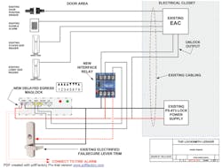
My sample diagram illustrates many of the points I made in the article. The design is lifted off a job I did over the summer, only that job utilized an electric strike and not an electrified lever. Also I was supplying everything except the existing electric strikes.
But the desired functionality was the same, and the configuration for the delayed egress maglock was the same, so I would not have another learning curve to replicate the original system. Now that I was familiar with this delayed egress maglock, I was confident I could install and program it quickly and it would work properly.
So I had the drawing for the other project on file and was able to modify it rather quickly. Every time you re-use a drawing you hopefully will further refine it.
When you are looking at the system in its entirety, you are able to focus on some of those details which might occur to you during the sales phase, but you might overlook when you prepare the proposal and layout the project.
This door had another type of delayed egress system on it, but there were issues with it, and the owner leaped at my suggestion to transition over to a highly reliable self-contained Integrated Delayed Egress Electromagnetic Lock.
My diagram does not show wire gauge, or details on the existing equipment which will not be changed. It does show specific wiring for the new components, the interface relay and the delayed egress daglock, as well as the jumper settings for the delayed egress daglock. It is a combination of a riser diagram and a system wiring diagram which is what I wanted for this project.
I make a note that the fire alarm will have to connected, and that the lever is fail secure.
e EAC (Electronic Access Control) monitors the DPS (door position sensor) and will initiate and audible alarm and signal security if the door is forced or propped. The alarm cancels by itself when the door is reclosed. If the delayed egress is triggered, it may be reset with a valid credential in either reader.
Since part of the pitch for this upgrade was not only reliable operation but also re-use of existing components, I clearly label the existing and new components, and show their relative locations, at the door or in the electrical closet.
There are different approaches to documenting projects, and this is an example of just one.


