Although not required by building codes, low energy door operators are an upgrade which adds safety and convenience to an opening.
Automatic door operators are divided into two categories: Full Energy Door Operators and Low Energy Door Operators. Although not required by building codes, low energy operators and how they are installed should comply with ANSI 156.19 which is the American National Standard For Power Assist and Low Energy Power Operated Doors. Full Energy Operators guidelines are ANSI 156.10 American National Standard for Power Operated Pedestrian Doors. These standards apply to swinging doors.
Standards such as ANSI 156.19 are consensus approved guidelines for manufacturers, installers and users of these devices. Standards which are guidelines should not be confused with Codes, which are laws.
The Standard addresses issues such as reliability, performance characteristics, recommended site conditions, and installation best practices which are intended to ensure consistency of products and operation of these types of systems.
ANSI Standards are revised on a regular basis, and AAADM certified inspectors and installers must undergo in-service training, and recertification to ensure they stay current with the latest editions of the guidelines.
Since door operators are electrically powered, mount on doors, and perform control functions of doors, there deployment is also covered by Codes such as:
· The NFPA 101: the Life Safety Code,
· The NFPA 80: Standard for Fire Doors and Other Opening Protectives,
· The NEC: The National Electric Code, and
· The ADAAG: Americans With Disabilities Act Accessibility Guidelines.
In practice these codes and guidelines dovetail well and do not present conflicts to the system designer, but compliance with one does not all ensure compliance with the others, so a general working knowledge of all of them is highly recommended.
In some cases, a door operator may help achieve compliance with a code even though the installation of the door operator was not a direct code requirement. An example of this would be on a fire door where NFPA 80 requires the door be closed and latched at all times, but site conditions make it not possible to achieve with the use of a door closer because in order to get the door to close against stack pressure or outside weather conditions the closer must overcompensate one setting to achieve another. In a situation such as this a low energy door operator may be the answer.
Programming Vestibule Door Operators For Sequential Operation
A common request is for vestibule installations where both inner and outer doors are equipped with automatic operators that they operate sequentially. The usual arrangement of knowing act handicapped buttons is for one actuator on the exterior of the building for entry, one actuator on the interior of the building for egress, and a pair of actuators inside the vestibule.
If actuators are used with RF transmitters and receivers, programming is easy, as receivers used for door operators are typically capable of providing an instant output or a delayed output.
If wired actuators or a combination of wired and hard-wired actuators are required, then an interface relay will be necessary.
For example if Touchless Actuators are desired for the primary entry and egress, then, since power is required to these units, wireless inside the actuator would not work.
Sometimes the spec will require hard-wired actuators. Sometimes there will be wire runs for card readers or intercoms, so hard-wiring makes sense.
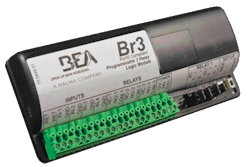
If the operator control system is wired, a module such as the BEASENSOR BR-3 can be used.
BEA SENSORS
The BR3 programmable three-Relay Logic Module contains logic for multiple applications including simple timing, door mounted sensor inhibiting and advanced relay sequencing allowing the technician to carry only one module.
- Multi-functionality offers increased value by combining legacy MC-Linx functionality in addition to new and more advanced functions for a variety of applications.
- Contains 3 relays; 2 large power relays and 1 small signal relay.
- Built-in surge suppression in all three relays eliminates the need for external components when installing electric locking devices.
- Provides the ability to select a ‘WET’ voltage output of up to 1 AMP on Relay 1 to power electric locking devices without the need for an external power supply.
- Advanced input power circuitry for better protection, including a resetable fuse.
BR-3 operating modes are ideal for most common applications. These include:
MC10 Simple Timer: Time delay relay.
MC11 Ratchet / Latching: Push to open / Push to close.
LE21 Inhibitor with Door Position Input: Automatic swing door with push plate, approach side SuperScan is inhibited when door is closed.
LE22 2 Relay Sequence Inhibitor with Door Position Input: Automatic swing door with push plate, approach side SuperScan and Electric
Strike. SuperScan is inhibited when door is closed.
MC25 2 Relay Sequence: Automatic swing door with a push plate and electric locking devices.
MC28 2 Relay Sequence with Door Position Input: Automatic swing door with a push plate and electric locking devices with a door position switch to prevent the delay from running when recycled before closing.
MC29 Relay 1 Deactivation Timer: Automatic swing door or sliding door with an electric locking device and door
position switch to prevent lock from reengaging before door closes completely.
MC35 3 Relay Sequence: Two door vestibule with automatic swing doors and single electric locking device.
MC50 Interlock Timer with Door Position Inputs: Interlock module that will only allow one door to open at a time and can be used with any automatic or manual door.
MC55 Interlock Ratchet with Door Position Inputs: Interlock module that will only allow one door to open at a time with a ratchet function and can be used with any automatic or manual door.
MC65 2-Way, 2 Relay Sequence: Two door vestibule sequencing with automatic swing doors traveling in either direction.
MC75 2 Relay Sequence: Automatic swing door with a push plate and electric locking devices with a ‘WET’ input.
For more information, visit www.beasensors.com.
Touchless Switches
The MS SEDCO 216 Series Infrared "Touchless" Door Activator Switches are active infrared devices designed to activate full and low energy automatic doors. Their hands free operation makes them ideal for ADA applications.
Other applications include clean-room access points, request-to-exit devices (3 amp contact) and point-of-purchase displays. The 216 is microprocessor controlled allowing for superior operation in a smaller unit. The 216 Series faceplates are available in three sizes.
The MS SEDCO 216-RK RETROFIT KIT is an easy, inexpensive way to upgrade existing hardwired mechanical actuators to touch-free (and therefore germ-free) switches by allowing connection using only two conductors per switch rather than the four conductors per switch normally required by Touchless Door Activators.
The 216-RK contains a new version of the 216 touchless switch designed to operate off of two wires only, and a module placed in the header. Two switches (one of each side of the door) wire to this module, along with a power source (12-24 V AC or DC) and an activation output.
The switches included with the kit incorporate a new feature which is coming soon to standard hardwired 216 series switches – adjustable reaction time.
Reaction time is defined as the time from when someone places a hand in front of the switch until it sends its output. 216-RK switches will ship with the fastest reaction time setting, which is 0.05 seconds and noticeably quicker than the current 216.
Slowing down the reaction time is useful if the switch is located where inadvertent activations are a concern. Reaction time can be slowed down, requiring users to hold their hands in front of the switch for a longer time for activation to occur.
For more information, visit www.mssedco.com.


