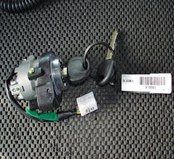
The 2008 Kia Optima ignition can post some challenges, particularly the first time a locksmith works on one. There are a lot of parts. Of course, the first thing is you have to remove it from the column. If you have ever taken a lock off a column, this is pretty much the same with the headless bolts. Once removed, you can then proceed to take it all apart. You will need a working key
Photo 1 shows the cylinder after it has been removed from the car. You can see on this picture we have a key code tag attached to the cylinder. This was a new one we acquired for this article. This key blank should be an HY15.
This may be a Crypto Transponder system. The next thing to do is to remove the transducer coil or light ring if non-transponder. It is held on by one Philips screw. Set it aside and then make room for a lot more parts. I suggest you put them somewhere so they cannot be disturbed and in the order you remove them. Then just reverse them all when putting the cylinder back together.
You must next take the key buzzer off. You do this by putting the key into the cylinder, turning it on, and then pushing the tab on the buzzer to slide it off. Again carefully put it aside in a clear area to be reassembled when you are done.
Next, we will run into several rubber pieces that just sit in place to keep everything together. They are not glued nor attached firmly. You just have to have a sharp object to lift them up to remove. Set these carefully aside.
Photos 2-5 show them in order of removal. These small pieces of rubber could easily get lost and I have no idea what you could use in their place to fix it. Once again, be very careful and put all of this in a place where you will not disturb them.
We are now down to the base cylinder. There are four more components to deal with - an outer housing, a cap, an inner housing and then the cylinder itself. So first we have the outer housing and an active retainer to depress.
In Photo 6, you can see the housing with the active retainer to depress and just the end of the cap on the left side. So you must have a working key for the next step. You first either push or pry from the front the inner cylinder. It will move about a ¼” inch out as you can see in Photo 7.
This will push the retainer into the outer shell as you can see on the right in Photo 8. The inner cylinder slides out to the left about a ¼”. The retainer is now in position for you to push it down with a punch the slide the inner cylinder to the left and remove it.
You will now have the inner cylinder in hand but there is another cylinder within this one to remove.
In Photo 9, we slide the last inner cylinder out to the left. Now this needs to be taken apart so we can work on the wafers themselves. There are a few more things to do but we are getting closer!
First, remove the snap ring on the back with some torque tools. Take your torque tool and take the snap ring off the end of the cylinder. (See photos 10 and 11)
Now we have to take some more rubber off the outside of the cylinder. As you can in Photo 12, it keeps the facecap from coming off. You have to pull it off then you can rotate the cap counter clockwise to remove it.
Get a sharp object to pull the rubber up and off the outside shell, as shown in Photo 13. You can then rotate the cap counter clock wise to remove.
Now we will finally get down to what we need to do some work on the wafers themselves. We do have one more little tricky part first. Now that you have turned the cap counter clockwise, you can slide it off. (See Photo 14) Put it aside for later.
A pin on the end of the cylinder is holding the cylinder in place.
In the series of photos 15, 16, and 17, you will see how to raise it up to slide the cylinder out. In photo 15, you can just see the end of the pin. This is the top of it and in photo 16, it protrudes down into the cylinder end. In photo 17, we use a sharp object to lift it up and get the cylinder out.
So now after many rubber pieces, etc. the cylinder is in hand to re-pin or repair. It has a standard wafer system. So you should not have any issues from here on out, right?
Wait, you still have to reverse your procedures to get it all back together. Did you lose anything yet?? We sure hope you learned something and this will make it a little easier for you.


