Trine Wireless Controller and Transmitter: Simplified Access Control
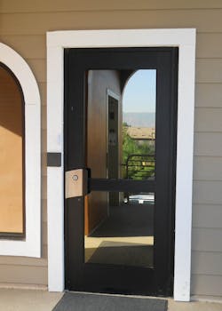
In a previous article, I was invited to the installation of a Trine 4850 Electric Strike to control access through a glass aluminum storefront door. Authorized persons would use their “badge” HID card to gain access through the front door using the HID card reader installed adjacent to the opening side of the door. A rim exit device with exterior lock cylinder is the only lock installed onto this door.
However, to provide access for a visitor or person who was not authorized, the receptionist or any person close to the front door would operate the exit device to open the door. As the receptionist was not always at her desk or nearby, a visitor had to wait until someone arrived. For these instances, there was a doorbell button.
From previously viewing the Trine website when writing the 4850 installation article, I remembered they sold wireless controller receivers and wireless transmitters. These Radio Frequency (RF) devices provide wireless remote release for locking devices including electric strikes.
Wireless Transmitter
The wireless transmitter, Trine Part # 018-2, operates on 315 MHz, a common frequency for United States and Japanese automotive remote keyless entry fobs. This FCC and IC Approved dual button transmitter is designed to operate with the Trine wireless controller/receiver.
The Trine 017TDC-3 Wireless Controller/ Receiver is a dual relay controller, which can remotely release one or two lock devices. For this installation, the controller will be used to release only the Trine 4850 electric strike. Having a wireless transmitter in the shape of a fob permits the receptionist to be able to provide access from anywhere the controller/receiver can receive a signal.
The Trine 017TDC-3 dual relay controller has two 5 Amp Normally Open (NO) and Normally Closed (NC) contacts rated at 12-30 Volts AC /DC. The relays can be coupled to operate simultaneously for a single operation or individually for two separate operations. Each relay has an adjustable time delay from a minimum of five seconds to a maximum of 30 seconds.
Trine includes a copper shunt connecting the negative terminal and the two COM terminals. Connecting the COM to the negative allows the relay to be tripped for a device that has its own power. When the shunt is removed, the Trine dual relay controller does not power either relay, making the unit a wireless remote relay.
An external antenna comes with the 017TDC-3 having a line-of-sight range of up to 300 feet. Line-of-sight range is literally that clear, unobstructed line from the controller to the transmitter. The term line of sight is a standard reference for in a perfect world. However, most installation will not be line of sight. For this application, we were hampered with walls, server racks, wiring, HVAC ducting, roll insulation, etc., making this an installer’s nightmare of signal obliterating objects.
Although the actual distance from the power supply and access control circuit board to the front door was no more than 50 feet, we were forced to move the Trine 017TDC-3 up as the walls, aluminum window and door frames, servers and their metal racks caused interference, limiting the range to about 30 feet.
So we moved the controller up into the attic through one of the wiring routing tubes in the ceiling directly above the mounted enclosures. With the system temporarily wired, someone moved around the attic holding the Trine 017TDC-3 in order to find an optimal location. The final result was the receptionist could be at the desk, in the conference room or the forward offices, and remotely unlock the front door.
Power Supply
For this installation, the wireless controller/receiver operates using the same 24VDC filtered and electronically regulated power as the electric strike and the badge reader. The power supply and badge reader enclosures are installed in the server room behind a narrow dividing wall. A four wire 18 gauge jacketed cable was run from the Trine 017TDC-3 installed in the attic down through the wiring tube and wired into the enclosure containing the badge reader circuit board, terminal strip, backup battery and Altronix LPS3R circuit board. The LPS3R Linear Power Supply/Charger converts low voltage AC input to e 12VDC/24VDC output. This power supply/charger produces 2.5 amps continuous supply current that is filtered and electronically regulated. The LPS3R will charge backup batteries at a maximum charge current of 500mA.
Wiring the controller began with determining which badge reader circuit board output connector controlled the power to the front door. We could not just follow the wires, as there were two sets: one for the front door and one for the back door. The badge reader circuit board had two output connectors: one for the front door and one for the back. We disengaged one connector and tested the operation of the front door using the locksmith’s employee badge. The electric strike released. The other connector operated the front door. Following the wiring, we determined which terminal strip connectors were used to wire in the HID badge reader. The controller would be wired into the same connectors. The power connector was detached from the badge reader circuit board. This way the connections could be made safely.
Two terminal strips were connected wires from the badge reader circuit board and the LPS3R Linear Power Supply/Charger. The wiring from the Trine Wireless Controller/ Receiver would be wired into the terminal strip obtaining power from the LPS3R and jointly controlling operation of the electric strike with the badge reader circuit board.
For this installation, we set up the wiring as a wireless remote relay. Four wires were run from the controller:
Power In was positive (+) red wire and negative (-) black wire.
The relay wired was COM1 white wire and NO1 (Normally Open) green wire.
- The controller’s positive (+) red wire was connected to the constant positive (+) wires on the terminal strip.
- The controller’s negative (-) wire was connected to the constant negative (-) wires on the terminal strip.
- The controllers NO1 wire goes to the constant positive (+) wires on the terminal strip.
- The controller’s COM1 goes to the electric strike positive (+) output.
A jumper wire was run between the electric strike negative wire and the constant power negative (-) wire.
Switches
Once the wires were installed onto the terminal strip, the power connector was attached. The next step is to set the security code switches. Both the Trine 017TDC-3 Wireless Controller/ Receiver and the 018-2 Transmitter have eight slide type DIP (Dual inline package) switches in one group providing 6561 security codes. Each switch has two possible positions; on or off. To set the security code, all eight DIPswitches on controller and the transmitter must be in the same positions.
A second group of four DIPswitches in the controller is the relay control switch. The positions of the four switches sets the mode of operation - one device or two and which button operates what device. The four DIPswitches were in the on position, all up. In this position, any button operates both relays, eliminating the need to remember which button powers the solenoid in the front door electric strike.
The final adjustment is the trigger time delay setting. Two time delay knobs in the controller set the trigger time delay. Rotating the knob clockwise increase the delay. For our purposes, the delay was set at five seconds.
The system was tested first with the transmitter in close proximity to the door. Eventually the optimum position of the controller was determined and installed onto a 2x4 about four feet above the attic floor. Pushing either button illuminates the LED on the transmitter and when in range powers the solenoid and releases the electric strike’s keeper.
A wireless controller and transmitter can be a good choice for remote operation of an electronic lock mechanism.
For more information, contact your local locksmith distributor or Trine Access Technology, 1440 Ferris Place, Bronx, NY 10461. Telephone: 718-829-2332. Web Site: www.TrineOnline.com.
To read additional Locksmith Ledger articles about Trine products, visit http://tinyurl.com/trine0212.
Tools and equipment: Multi-meter, wiring, screwdrivers, side cutters, wire strippers, ladder
Installation Time: approximately 45 minutes
About the Author