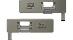
As the name indicates, surface-mount electric strikes are mounted onto the surface of the jamb without cutting an opening to accommodate the mechanism. They are designed to operate with rim exit devices whose strikes have been surface applied.
Rim exit devices are surface-mounted exit devices mounted onto the secured side of an outswinging door in order to permit free egress. The latching mechanism for most rim exit devices is a Pullman bolt, which swings out and in from the center case. Because the Pullman bolt swings out instead of extending out, it has an arced shape to accommodate the swing. Depending upon the manufacturer and the application, rim exit devices can have a ½” or ¾” throw Pullman bolt.
Surface-mount electric strikes can be used to secure exit devices mounted onto wood, composite, hollow metal or aluminum storefront doors. Depending upon the strike, they can secure a ½”, ¾” or 1”. They come in different thicknesses in order to accommodate different rim exit device applications.
Trine’s 4800 and 4801 Surface Mount Electric Strike models have ¾” thick bodies to accommodate different bolt configurations. A 1/8" thick spacer is included for installations requiring mounting the strike closer to the exit device center case. The Trine 4801 electric strike was developed to accommodate Corbin Russwin SecureBolt™ and Yale SquareBolt® equipped exit devices. The 4800 was developed for Pullman Bolt-equipped exit devices.
To expand the surface-mount product line, Trine introduced the 4850 Surface-Mount Electric Strike with a ½” thick body, designed for those applications that have minimal distance between the center case and the jamb. Since the 4850 does not have a back plate, the Pullman Bolt has a full ½” depth. To accommodate different Pullman Bolts and installations, Trine includes a ¼” and 1/8” thick spacers in order to have proper clearance between the electric strike and the center case.
A standard mount rim exit device will have the latch in close proximity to the strike. This way, when the door is closed and the latch is secured, the gap is minimal, ensuring the door is closed. For this reason, there is very limited amount of space between the strike mounted onto the jamb and the exit device cover.
For this article, I was invited to the installation of a Trine 4850 Surface Mount Electric Strike onto an aluminum frame. The 4850 is a Grade 1 electric strike with the capability of automatically adjusting an input of 11 to 28VDC. For 12VDC operation, the pull in requires .500 Amps while hold requires .178 Amps. For 24VDC, the pull in requires .255 Amps while hold requires .084 Amps. The 4850 electronics are designed with surge and kickback protection.
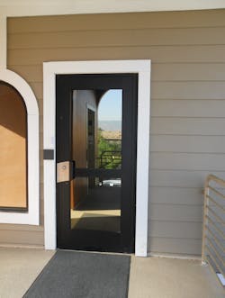
The Trine 4850 will be used to control access on the aluminum-glass storefront door equipped with a rim exit device. To our advantage, the building has a gable roof with more than standup headroom in the attic. The door was located beneath the ridge, making it relatively easy to run the wiring down to the jamb and connect the electric strike. From there, an HID reader was installed on the exterior wall adjacent to the lock side of the door. The power supply was installed in the computer room.
To resist unauthorized access, anti-vandal trim with astragal was installed onto the exterior to protect the cylinder and the device’s Pullman Bolt. The stainless steel trim’s coating covers the pull handle area. The anti-vandal trim is Americans With Disabilities Act (ADA) compliant.
Electronic access will be controlled by the use of proximity identification cards. A decision was made not to install a release button at the desk just inside the office. Instead, a doorbell was previously installed to notify the receptionist if some unauthorized individual wanted access. Having a glass aluminum door gives the receptionist the choice to permit or restrict access.
The configuration of the doorway has a narrow jamb stop, just wide enough to mount the strike, shown in photo 3. A spacer (aluminum plate) was necessary in order to mount the Trine 4850 onto the jamb. The electric strike was mounted onto both the jamb stop and the aluminum plate to have the keeper in the proper location to accommodate the Pullman Bolt and secure the door.
The Trine patented 6-pin anchoring system provides additional lateral strength and stability to resist forced entry. For this installation, two pin anchoring system holes were drilled into both the jamb stop and the aluminum plate. Two ¼-20 mounting screw holes were drilled and tapped into the aluminum plate to secure the electric strike onto the jamb.
To locate the 4850 onto the jamb, laterally position the electric strike keeper in the approximate position of the strike. Check to make sure the Pullman Bolt is centered on the strike. Once located, using the top and bottom slotted holes, draw two ovals for the socket screws. Drill one #7 hole in the center of each and tap the holes for a ¼-20 thread. Mount the electric strike using the two provided socket mounting screws. Close the door a number of times to be certain the electric strike is in the proper position. Make lateral adjustments as necessary.
When the electric strike is in the proper position, use a pencil to draw a line around the body. Remove the 4850. Use a spacer plate as a template to locate the four top and bottom pin anchoring holes. Use a #30 drill bit to drill the four holes.
Note: The Trine 4850’s factory default operation is Fail Secure. In this mode of operation, power is required in order to release the Pullman Bolt.
The 4850 can be field changed from Fail Secure to Fail Safe by removing the three cover screws and the cover plate. Lift out the solenoid and remove the plunger and the blue spring assembly (Blue spring assembly = Fail Secure operation). Insert the plunger with the red spring assembly (Red spring assembly = Fail Safe operation). The next step is to lift off the actuator cam in the Fail Secure position and flip it over to be in the Fail Safe position (Fail Safe has an “X” on top). Re-insert the solenoid, making sure the plunger and Red spring are in the proper position. Test the operation of the strike before installing the cover.
Once the cover has been attached, install the four pin anchors into the electric strike. Connect the electrical and slide it onto the jamb. Thread the two socket screws and mount the 4850 onto the jamb. Power the electric strike and test the operation.
Important: Before planning an installation of any electronic locking mechanism, always check with the Authority Having Jurisdiction (AHJ).
The Trine 4850 Surface Mounted Electric Strike offers the ability to accommodate most rim exit devices in order to provide your customers with electronic access control for non-fire rated openings.
For more information, contact your local locksmith wholesaler or Trine Access Technology, a 1440 Ferris Place, Bronx, NY 10461. Telephone: 718-829-2332. Fax: 718-829-6405. Website: www.trineonline.com.
To read additional Locksmith Ledger articles on Trine electric strikes, visit http://tinyurl.com/trine1211.


