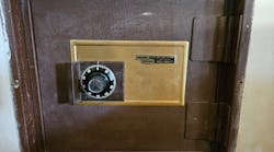
A friend obtained a Sentry ® 5560 Fire-Safe ® at a "bargain price," figuring that I could make the minor repairs and he would have a safe. He was so excited as he spoke, telling me the safe was open, so repairs could be even faster as there was no "additional" time needed to open it.
I explained that fire safes have a limited warranty life expectancy, and the Model 5560 is out-of-date and no longer an active part number for Sentry. He did not care as he kept most of his papers in a safe deposit box anyway. He figured the safe would provide security for interim needs.
There was no rust on the exterior or the interior of the safe, and it was clean. The safe was a good size, with a shelf. Examining the exterior, the space between the door and the body of the safe was about even on the top and the swing side of the door.
It appeared the combination had been dialed, and the boltwork was still retracted. The handle would extend the bolts with the door open. However, when the door was closed, the boltwork could not be extended.
To gain access to the boltwork and the combination lock, the screws and the cover were removed from the inside of the door. The links with welded bolts were bent, not allowing them to be extended into the safe body. Since the safe door could not be locked with the door closed, the wheels of the combination lock were trapped. To prevent an accidental lockout, the combination lock wheels were removed. The dial was removed and the spindle was cleaned and lubricated.
The boltwork is comprised of four links with welded bolt tips that are attached to two rotating discs located along the middle of the safe door. The upper two links are controlled by the upper disc. The lower two are controlled by the lower disc. The handle is connected to an elliptically attached disc, which is linked to the two discs that operate the links. Turning the handle clockwise when the safe is dialed open retracts the bolts into the body of the door. Turning the handle counterclockwise extends the bolts out of the door.
The four links were numbered and removed from the safe door. Once the links were removed, they were the same length. They would be installed individually, making the necessary adjustments one at a time. All four of the links were straightened. The boltwork and the bolts were lubricated with white lithium grease. The first link was installed. The door was closed and the attempt made to extend the bolt. The bolt would not extend. Adjustment was needed to angle the bolt towards the body of the safe. After a few adjustments, the handle would smoothly lock the bolt in place. The second link was installed. The same direction of adjustment was necessary for this bolt to extend. After installing and adjusting each of the two bottom bolts, the safe was ready for a new combination.
The Sentry 5560 Fire-Safe is equipped with a simple, three-wheel combination lock mechanism. The three wheels control the movement of the boltwork. When the operating combination has not been dialed, turning the handle will not allow the boltwork to retract. It is stopped against the outside edge of the oversized wheel that has false notches along the outer edge. Once dialed to the opening combination, the three wheels' gateways align. The fence, which is directly attached to the boltwork, can enter the gateways providing a large enough opening to retract the bolts. The handle can be turned, retracting the boltwork, permitting the door to be opened.
The combination lock wheels are attached to a shaft on the inside of the door. A series of wave washers, washers, and a Tru-arc ring position the stopping point for the first wheel. This wheel and the middle wheel are round and have fixed position flies (one on each side of the wheel). Between the first wheel and the middle wheel is a plastic washer that provides the necessary distance for the fly from the middle wheel to contact the fly from the first wheel.
There is a plastic washer between the middle wheel and the end wheel. The face of the second plastic washer should line up with the end of the shaft. The hole in the center of the end wheel is smaller and rectangular-shaped with rounded corners to slide over the spline shaft of the dial. A second plastic washer is positioned between the end of the shaft and the end wheel. A metal washer/fly is placed on top of the end wheel with the fly sliding through one of the holes along the edge. A castle nut secures this wheel against the shaft, which secures all three wheels in place. The end wheel is slightly larger than the other two wheels. It has false gates along the edge to resist manipulation. The end wheel also acts as the cam, as there is no separate cam for these combination locks.
Note: To determine the position of the Tru-arc ring, measure the thickness of the two wheels and the two plastic washers. Use this measurement from the end of the shaft back.
The first wheel and the middle wheel must have sufficient pressure against the end wheel to keep them tight to each other. If there is sufficient pressure, after turning the dial two full rotations, begin the first wheel turning. The end wheel will turn approximately one revolution until its fly contacts a fixed fly of the center wheel. Continuing to turn the dial will rotate the end and middle wheels approximately one revolution until the fly on the other side of the middle wheel contacts the fly on the first wheel. Continuing to turn the dial will rotate the end, middle, and first wheels.
The first wheel and the middle wheel must have sufficient pressure against the end wheel to keep them tight to each other. If there is sufficient pressure, after turning the dial two full rotations, begin the first wheel turning. The end wheel will turn approximately one revolution until its fly contacts a fixed fly of the center wheel. Continuing to turn the dial will rotate the end and middle wheels approximately one revolution until the fly on the other side of the middle wheel contacts the fly on the first wheel. Continuing to turn the dial will rotate the end, middle, and first wheels.
Since the gateways in the first and middle wheels are positioned arbitrarily, the combination is set by decoding an installed set of wheels. With the door open and the cover removed, begin turning the dial to the left (counterclockwise) until the gateway aligns with the boltwork fence, approximately three revolutions. Read the number on the dial that aligns with the opening index. This is the first number of the combination. Rotate the dial to the right (clockwise) one revolution until the middle wheel begins to turn. Continue to rotate the dial to the right until the gateway of the middle wheel aligns with the boltwork fence. Read the number on the dial that aligns with the opening index. This is the middle number of the combination. Rotate the dial to the left (counterclockwise) until the first wheel gateway aligns with the boltwork fence. Read the number on the dial that aligns with the opening index. This is the third number of the combination.
Note: Dial the combination at least three more times with the door open to be certain the gateways align with the boltwork fence.
To dial the combination of the Sentry 5560:
- Step 1. Turn the dial to zero.
- Step 2. Turn the dial to the left (counterclockwise) three times to the first number of the combination. Three rotations of the dial are necessary to get the third wheel turning to its opening number.
- Step 3. Turn the dial to the right (clockwise) two times to get the second number of the combination. Two rotations of the dial are necessary to get the second wheel turning to its opening number.
- Step 4. Turn the dial to the left to the last number.
- Step 5. Rotate the handle and open the door.
The above servicing procedures can be used on most of the Sentry three-wheel combination safes. For more information on Sentry safes, contact the Sentry Group, 900 Linden Avenue, Rochester, New York 14625. Telephone: 800-828-1438. Website: www.sentrysafe.com .


