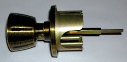
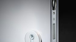
Continuing in our series of servicing residential locksets, this month we will discuss the front removable lock cylinder Weiser Lock square spindle. These Weiser knobsets have been produced for many years. They can be identified by the opening between the lock cylinder face and the knob. The early model knobsets were equipped with two posts connecting the outside assembly to the inside assembly. To improve security, Weiser introduced the four-post version, adding two additional posts at 90 degrees from the two original posts. To provide protection against spindle area attacks, a shield became part of the four-post version chassis.
The two- and four-post Weiser knobset chassis are manufactured of zinc. The internal components are manufactured of stamped metal. The trim is brass. These knobsets are designed to meet or exceed ANSI A156.2, Series 4000, Grade II. Depending upon the model, Weiser knobsets can be equipped with a brass plug and zinc die cast or self-lubricating Delrin housing. The standard keyway is the Weiser "E", a five pin tumbler lock mechanism. Weiser also offers a "C" keyway plug option. These Weiser knobsets are equipped with surface-mounted screws located on the inner trim.
The Weiser square spindle, front removable lock cylinder knobsets are designed to be installed into a 2-1/8" diameter cross bore opening with a 1" diameter edge bore opening. They can accommodate up to a 2" thick door. The adjustable backset latch can fit a 2-3/8" or a 2-3/4" backset. The keyed knobsets are equipped with a deadlocking function latch that can be configured to accommodate a square, 1/4" radius, or a drive-in faceplate.
For this article, we will service the Weiser Aristocrat residential four-post knobset. Servicing procedures are the same for the four- and two-post versions.
The Weiser knobsets equipped with the front removable lock cylinders require the lock to be removed from the door in order to remove the lock cylinder. This is because the square shaft within the spindle must be pulled in order to release the lock cylinder from the exterior knob.
To gain access to the lock cylinder:
Step 1. Remove the two Phillips head screws from the inner trim. If the knobset is a two-post version, the screws are located at 3 and 9 o'clock. If the knobset is a four-post version, the screws are located at 6 and 12 o'clock.
Step 2. Remove the inner trim and the outer knob assembly.
If no operating key is available, pick the lock cylinder, and rotate the plug at least 10 degrees in either direction to stop the lock cylinder from becoming locked. Continue with Step 4. If an operating key is available, continue with Step 3.
Step 3. Insert the operating key into the lock cylinder.
Step 4. Place the outside knob assembly in one hand and hold the square shaft between your thumb and first finger.
Step 5. Pull out on the square shaft until it stops. Maintain pressure.
Step 6. Rotate the plug until the lock cylinder slides out of the outside knob. The release position is approximately 30 degrees counterclockwise from the locked position.
Once the lock cylinder has been removed from the outside knob, the lock can be serviced. The plug is retained in the lock cylinder with a Tru-Arc ring.
To service the lock cylinder:
Step 1. Remove the Tru-Arc ring using Tru-Arc pliers, making sure to not pull the plug out of the housing or re-lock the cylinder.
Step 2. Use a follower to remove the plug.
Note: If the knobset has been part of a master key system, it is recommended to empty the pins and springs from the housing.
The Weiser five-pin tumbler "E" keyway lock cylinder is standard. A five-pin tumbler "C" keyway plug is available as an option. All of the lock cylinders have brass plugs and either die-cast housings or self-lubricating Delrin housings.
When originating a new key, determine the depths of the cuts. Use the following space, depth, key blank, and cutting information for originating a new key and/or combinating the lock cylinder.
SPACE
Shoulder to center of first cut: .237"
Center of cut to center of adjacent cut: .156"
Flat (width of cut): .080"
| 1- .237” | 2- .393” |
| 3- .549” | 4- .705” |
| 5- .861” | 6- 1.017” |
| 7- 1.173” |
DEPTH
Drop (increment) .018"
| 0-.315” | 1- .297” |
| 2- .279” | 3- .261” |
| 4- .243” | 5- .225” |
| 6- .207” | 7- .189” |
| 8- .171” | 9- .153” |
KEY BLANKS
The following key blank numbers are comparable to the original key blank manufactured for Weiser:
| Weiser | Axxess |
| 1573 | 67 |
| Barnes | Ilco |
| WR3 | 1054WB |
| Ilco EZ | Jet |
| WR3 | WR3 |
CODE CUTTING EQUIPMENT
To originate keys for the Weiser locks, use the following:
- HPC Code Machine C50
- Ilco Universal II 411
- ITL 167 Insert 2
The factory specifications for the flat-end pin tumblers used by Weiser locks area flat of .080" and the angle of cut is 90 degrees. To obtain operating dimensions, use the HPC cutter CW-1014, the Framon cutter FC9090, or the Ilco cutter 36MC.
If these cutters are not available and the cutter being used does not create at least .080" flat, then the keys may not have a wide enough flat to accommodate the flat bottom pins. If the proper cutter is not available, there are two options. Either widen the flat of each cut to .080" or use conical shaped pins to accommodate the narrow flat.
Once the plug has been combinated and installed into the housing, test the operation of the keys. Attach the Tru-Arc ring and make sure the lock cylinder operates properly before installing the lock into the door.
To re-assemble the lock:
Step 1. Hold the outside knob assembly in one hand and pull out on the square shaft.
Step 2. With the key inserted into the plug, slide the housing into the outside knob, making sure the cuts in the key align with the bible and the bible slides into the slot within the knob.
Step 3. Maintain pressure on the square shaft and rotate the plug counterclockwise approximately 30 degrees until the cylinder slides completely into the knob. Release the square shaft. The lock cylinder should remain within knob.
Note: Make sure the key can be removed from the lock cylinder before installing the lock into the door. The key can become trapped if the plug is rotated too far. If this occurs, pull out on the square shaft and rotate the plug approximately 180 degrees, being careful not to let the lock cylinder slide out of the knob. Release the square shaft and rotate the key until it slide out of the keyway.
Step 4. Install the lock into the door. Test the operation of the lock to make sure it operates properly.
WEISER OPTIONS
Weiser knobsets are available in product lines including Professional Grade, Prestige Series, Welcome Home Series, Elements Series, and Basics. There are a number of knobset designs and, depending upon the product, up to nine finishes. Weiser knobsets are available as keyed, non-keyed, and dummy.
The front-removable lock cylinder Weiser Lock square spindle is available in several keyed functions. Weiser Lock's Lifetime Finish Warranty offers protection against corrosion, tarnishing or discoloring on all finishes in the Welcome Home Series of products sold after Dec. 1, 2001.
Depending upon the version, the following functions may be available:
500 Front/Back Lockset. Latch bolt is operated by knob from either side. Keyed knob outside with a push-and-turn locking knob or pushbutton on the inside. Inside knob always free. Turning inside knob unlocks both knobs. Deadlocking latch is standard.
510 Front/Back Lockset. Inside knob always free. Dual locking button operates as temporary or permanent. For temporary locking, push inside knob button. Turning key or knob inside releases push button. For permanent locking of outside knob, inside knob button is pushed in and turned to the right. Latch bolt retracted by key outside or knob inside. Locking button must be manually returned to unlocked position. Deadlocking latch is standard.
530 Front/Back Lockset. Latch bolt is operated by knob from either side. Keyed knob outside; turn button locking inside. Deadlocking latch is standard.
560 Classroom Lockset. Latch bolt operated by lever from either side, except when outside knob is locked by key outside. Inside knob is always free. Deadlocking latch is standard.
580 Storeroom Lockset. Keyed knob outside, outside knob always rigid, inside knob always free. Deadlocking latch is standard.
For more information, contact your local locksmith wholesaler or Weiser Lock, 19701 Da Vinci, Lake Forest, CA 92610. Telephone: 800-677-5625. Website: www.weiserlock.com. Fax: 800-713-7080.
