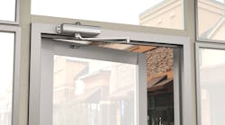
I was invited to the installation of a Norton LEO™ power door operator and door operator switch onto the right hand door of a pair of doors in the main entrance of a newly constructed building. Access through these doors is controlled using Yale rim exit devices with keyed dogging, and latching into a mullion. During the hours when people are moving throughout the building, the exit device will be dogged down.
The Norton LEO (low energy operator) was developed to provide opening assistance, at the same time having minimal resistance when the door is manually opened. The built-in closer body controls closing of the door. The Norton LEO meets ANSI/BHMA A156.1 (Low Energy Operators) and A156.4 (Door Closers), is UL Listed, and meets the requirements of the Americans with Disabilities Act (ADA).
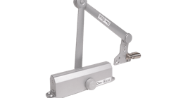
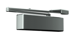
The LEO consists of three basic components: the inverter, the motor, and the closer body. The motor is used to push open the door, being connected to the closer and arm with a clutch operated chain. The closer, a modified Norton 1601, controls the closing of the door. The closer has adjustable spring power, backcheck, sweep and latch. The inverter controls the operation of the motor during and when the door is open. There are six adjustments for controlling the operation of the LEO. The inverter sets the door opening speed, hold open time, obstruction detection on open, door mounting, and motor torque at hold open position. A Trimpot Adjuster is provided with the LEO.
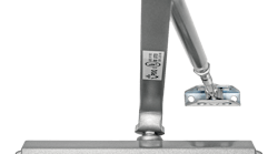
The Norton LEO is non-handed; only the arm determines whether the unit is installed on the push or pull side of the door. For this reason, the LEO is available in two configurations. The Model 5710 is installed onto the pull side of the door and is equipped with a track arm in order to open the door. The Model 5730 for the push side of the door is equipped with a double lever arm to open the door.
For this application, a LEO 5730 was installed onto the push side of a 36-inch wide hollow metal door with closer reinforcing and metal jamb, having an the opening angle in excess of 110 degrees. 120VAC power was run to the wall above the door closer. To provide assistance in operating the LEO, a wireless door operator switch, part number 574, was installed adjacent to the door and building personnel will have access to a key fob in order to remotely open the door.
For this reason, the Norton LEO was ordered with the RF receiver factory installed. This 433MHz receiver was mounted onto the motor and would not be visible with the cover installed. The only complication for the installation was the installed weather stripping that required the power operator to be positioned approximately one-half inch beneath the jamb header.
Before installing any lock hardware, make certain the door swings freely through the entire opening and closing cycle.
To install the Norton LEO:
Step 1. Remove the existing door closer.
Step 2. Mark the locations for the center hole in the operator backplate and the first opening for the shoe using the provided template. A decision was made to permit the door to open more than 110 degrees. This located the shoe at 9-1/2" inches from the centerline of the continuous hinge, and the power operator at 13-1/4" from centerline to center mounting hole.
Step 3. Place the LEO onto the door jamb at the proper distance. Because there was weather stripping installed, the operator had to overhang the jamb.
Step 4. Position the LEO low enough that the arm does not contact the weather stripping. Mark the location for the lower right corner opening in the backplate. This first hole was chosen for the adjustability and it would provide a strong first mounting position.
Step 5. Remove the LEO, and drill and tap a hole for a #1/4-20 screw.
Step 6. Place the LEO against the jamb with the inverter at the left and the closer at the right.
Step 7. Secure the LEO to the jamb by installing a #1/4-20 Phillips head screw.
Step 8. Remove the two screws from the top left and right side of the closer body. These screw holes will provide double duty, not only keeping the closer body attached to the backplate, but also helping to secure the LEO onto the jamb.
Step 9. Place a level against the backplate to level the LEO.
Step 10. Mark the location of the two openings in the closer body and the two other mounting holes on the left side of the backplate.
Step 11. Drill and tap the holes for #1/4-20 screws.
Step 12. Install the four #1/4-20 Phillips head screws.
Step 13. Install the main arm onto the pinion shaft at a 90-degree angle to the door jamb using a #1/4-20 flange head screw. There is only one position to install the main arm as there is a pinion flat on the closer shaft.
Step 14. Mount the shoe/adjusting rod onto the door using two 1/4-20 hex head screws.
Step 15. Slide the adjusting rod into the arm slide. Preload the arm by rotating the spindle shaft until the arm slide is at a 90-degree angle from the face of the door jamb. Once pre-loaded, install the forearm screw and secure the arm.
The next series of steps is to adjust the mechanical operation of the closer. We begin with adjusting the spring power of the closer. The spring power adjustment controls the amount of force that is exerted onto the door when opening and closing.
Step 16. Adjust the spring power to properly close the 36" wide door. The adjustment is done using a 1/8" hex wrench. Clockwise rotation increases power. Test operation of the closer. Use a gauge to make sure the closer operates according to the appropriate guidelines that indicate door closer force must not exceed five pounds when closing. Once the closer operates properly, continue with the sweep, latch, and backcheck adjustments.
The sweep adjustment controls the swing of the door from approximately 90 degrees to 10-15 degrees. The A.D.A. requires that from an open position of 70 degrees, the door must take at least three seconds to move to a point three inches from the latched position, measured at the leading edge of the door. A decision was made to set the sweep speed at approximately five to six seconds.
Step 17. Adjust the sweep speed to be approximately five to six seconds. Slower closing is clockwise rotation. Faster closing is counterclockwise rotation. Check operation of the closer.
The latching adjustment controls the swing of the door from approximately 10-15 degrees to latching. Too slow and the door will not completely latch. Too fast and the door will slam closed.
Step 18. Adjust the latching speed to about two to three seconds. Slower latching is clockwise rotation. Faster latching is counterclockwise rotation. Check operation of the closer.
The backcheck adjustment limits opening forces of manual operation, by slowing down the intensity at which the door can be opened. Proper adjustment avoids damage to the closer and operator. The backcheck adjustment should never take the place of a supplemental door stop.
Step 19. Adjust the backcheck to slow the doors opening movement as it reaches maximum opening. Check operation of the closer.
The LEO is factory adjusted prior to shipping. Test the power opening operation, following steps one through four.
Step 1. Turn off the circuit breaker and make the wiring connections of ground, common, and hot.
Step 2. Turn on the circuit breaker.
Step 3. Turn the power unit on and turn the breaker switch adjacent to the closer to "RESET".
Step 4. Use a jumper wire to jump terminal one and two to activate the opening procedure. Observe the operation of the low energy operator. If the LEO opens and closes smoothly, skip steps five through 13. Note: For this installation, there was no need to make any adjustments to the clutch or position rings.
Step 5. Jump terminals one and two to activate the operator's opening procedure.
Step 6. When the door reaches 20° open, turn the breaker switch to "OFF". Allow the door to close.
Step 7. Push the door open slightly and insert the 1/8" hex wrench into the clutch assembly to create a small gap between the two clutch components.
Step 8. Close the door and remove the hex wrench.
The Closing Position Ring Assembly position must be set to ensure the operator stop when the door closes.
Step 9. Loosen the Closing Position Ring set screw using the provided 5/64" hex wrench.
Step 10. Rotate the Closing Position Ring Assembly until the closed position magnet aligns with the Reed switch. Tighten the set screw.
Next, the Open Position Ring Assembly position must be set approximately 180 degrees from the Closing Ring Magnet.
Step 11. Loosen the Open Position Ring set screw and rotate until it is approximately 180° from the Closing Position set screw.
Step 12. Turn the breaker switch to the "RESET" position.
Step 13. Use a jumper wire to jump terminal one and two to activate the opening procedure. Note position of open door and allow door to close. Readjust the Open Position Ring to obtain desired angle of opening.
Once the low power operator is functioning, make any adjustments to the Trimpot. The default door hold-open time is 15 seconds. The hold-open time can be adjusted from five to 30 seconds.
The next set of step is to install the door operator switch, part number 574. This battery operated switch is equipped with a 433 MHz transmitter that must be programmed to the receiver in the LEO. The receiver is designed to learn up to 12 transmitters.
The door operator switch will be surface mounted for this installation.
Step 1. Install the 9-volt battery into the wall switch.
Step 2. Determine the mounting location of the door operator switch. It is best to location the mounting screws into a solid mounting surface or wall stud.
Step 3. Punch out the holes in the wall box designated "Mounting Screw Punch Out."
Step 4. Drill pilot holes for mounting the wall box.
Step 5. Fasten the wall box to the wall using two #8-32 x 1-1/2" wood screws.
Step 6. Assemble the seal adapter plate and install the two #6-32 screws. Do not tighten the screws as the wall switch cover plate slides onto the two screws.
Step 7. Connect the two wires to the wall switch cover plate.
Step 8. Slide the wall switch cover plate onto the two screws.
Step 9. Secure the screws through the openings in the wall switch cover plate using a provided hex wrench.
To program the wall switch transmitter and the key fob to the receiver in the LEO:
Step 1. Press the receiver's programming button for less than two seconds and release. The receiver's red LED changes from blinking red to a solid green.
Step 2. Press the wall plate closing the switch once. Verify the receiver's LED changes to solid red. The receiver is learning the transmitter's code.
Step 3. Wait a few seconds and test the operation of the wall Switch. The receiver's LED will blink green several times indicating the learning procedure is ending. Once the learning procedure has ended, the LED will blink red.
To clear the receiver's memory and delete all transmitters/key fobs, press the programming button for more than eight seconds until the LED starts blinking green. Release the button and the LED should begin blinking red. At this point the memory is cleared and transmitters/key fobs can be programmed.
Once all of the transmitters/key fobs have been programmed install the cover onto the low energy operator.
The Norton LEO can be ordered with a choice of two closer power sizes; three through six or one through four. The current draw of this low power operator is .6 Amps. There is Double Pole/Double Throw relay output capable of releasing an electronic lock mechanism to function in conjunction with the operator. The LEO is available in a variety of finishes including acrylic and powder coat.
For more information, contact your local locksmith wholesaler or Norton Door Controls, 1902 Airport Road, Monroe, NC 28110. Telephone: 800-438-1951. Fax: 800-338-0965. Web site www.nortondoorcontrols.com.


