I was invited to the retrofitting of the lock hardware on a pair of wide stile aluminum doors equipped with rim exit devices latching onto a mullion. To improve traffic flow, a decision was made to remove the mullion from this opening. In order to remove the mullion, the exit devices were changed out to vertical rod type. Because this is a public building, for safety and longevity, the Yale 7160 Concealed Vertical Rod Exit Device using the Yale 626F Trim was installed.
The Yale 7160 Concealed Vertical Rod Exit Device is equipped with a steel case. The Yale 7160 is designed for minimum 4-1/2" wide stile doors. These handed, field-reversible exit devices can be used on wood and metal doors. To secure the door, the concealed top latch enters a mortised top strike. For this application, the 7160 exit device was ordered less bottom rod. The Yale 7160 is ANSI A156.3 Type 7 and 8, Grade 1, UL/cUL Listed FVSR/FVSR7 for panic hardware. For fire exit device less bottom rod applications, a heat-activated door bolt (Popper) is required.
The 626F Trim is equipped with patented free-wheeling levers. This clutch mechanism allows the outside trim lever to float down 60 degrees when in the locked condition. For vandal and attack resistance, this heavy-duty solid forged escutcheon trim is through-bolted with threaded studs. To resist frontal attack, the escutcheon has beveled sides. When equipped with a 1-1/8" rim cylinder, a collar is required. The Yale 626F trim is available with eight lever designs. For this installation, the Yale 626F trim was classroom function requiring an operating key to unlock or lock the lever to control access.
To retrofit from rim to concealed vertical rod exit devices, several modifications were necessary. Each of the concealed latch mechanisms required a pair of mounting blocks placed into the stiles. In addition, the lock side of each stile had to be modified to accommodate the opening for the yoke pin and the 626F trim.
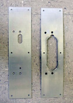
For this retrofit, the locksmiths had to make four mounting blocks for the two top latches, and modify four stainless steel Mag plates to accommodate the device and trim. The Mag plates will be placed onto both side of the door. They performed two functions. The first plate was the template for the openings required by the exit device and trim. The second covered the holes used to mount the rim exit devices.
The doors had to be removed from the jambs in order to modify the stile and install the mounting blocks. In this specific installation, there was sufficient space between the door and jamb, enabling the top pivot arm to be unscrewed and removed from the header in order to remove the door.
IMPORTANT: We strongly recommend at least two people perform the door removal and installation.
Before removing the door, check the operation of the floor closer. If the closer is adjustable, make any necessary adjustments for the door to properly close. If the floor closer is not operational, service as needed since the door must be removed in order to access the closer.
To retrofit the doors with the Yale Concealed Vertical Rod Exit Devices:
Step 1. Loosen the floor closer shaft retaining bolt. A spray of Liquid Wrench can make loosening the bolt and removing the door easier.
Step 2. Remove the screws from the jamb side of the center pivot.
Step 3. Remove the screws from the jamb side of the top pivot.
Step 4. Raise the door slightly in order to remove any shim washers from the closer shaft. Removing the washers enlarges the gap between the overall door height and the jamb height, making it easier to remove the door. Lower the door.
Step 5. Carefully slide the top pivot arm from the header.
Step 6. Slightly tilt the door out from the jamb. The farther the door tilts out from the jamb, the more resistance there is to lifting the door off the closer shaft. However, the door must be tilted out to be removed from the jamb. Use a crow bar to slowly lift the door as it is tilted away from the jamb.
Step 7. Once the door is away from the jamb, lift door off the closer shaft. Set door aside in a safe place. For this installation, the door was placed onto two sawhorses at a workable height.
Once door has been removed, check the arm and the floor closer. Check the bottom of the door to be certain the closer arm bolts are tight. Also consider checking if the closer is leaking. Service as necessary.
Step 8. Install the mounting blocks into the top of the stile.
Step 9. Place the top latch into the stile of the door. Mark the location for the latch bolt trigger notch. As the door closes, the latch bolt trigger contacts the jamb stop and releases the latch bolt, which extends into the strike, latching the door closed.
Step 10. Cut the 5/8" deep by 3/8" wide notch into the vertical centerline of the stile to accommodate the latch bolt trigger.
Step 11. Locate the exit device modified plate onto the inside of the door.
Step 12. Drill the four 5/16" diameter mounting holes for the center case and the trim. The device mounting holes are on the center line for the rods. The two holes closest to the swing side of the door edge secure the center case to the trim.
Step 13. Cut the yoke pin slot in the interior side of the stile. The yoke pin slides up and down to latch and unlatch the mechanism.
Step 14. Attach the yoke pin onto the arm and bracket assembly.
Step 15. Lay the latch on top of the stile and mount the top rod and arm and bracket assembly to determine the proper length for the top rod. Adjustment holes in the top rod are six inches apart with the longest standard length for an eight foot door. If necessary, cut the top rod to accommodate the door height using a hacksaw.
Step 16. Assemble the latch, top rod, and arm & bracket assembly. Install the cotter pin securing the tube to the rod.
Step 17. Install the two cotter pins securing the rod to the arm and bracket assembly.
Step 18. Slide the entire assembly into the stile of the door with the latch bolt contacting the mounting blocks.
Step 19. Position the yoke pin in the slot on the interior side of the door. With the latch bolt extended, the yoke pin should be lower on the stile without contacting the bottom edge of the slot. Retract the latch bolt and the yoke pin should rise up within the slot without contacting the top edge of the slot. If the yoke pin contacts an edge of the slot, adjust the length of the rod. Turning the rod in a clockwise direction lengthens of the rod. Turning the rod in a counterclockwise direction shortens the rod.
Step 20. Secure the latch to the mounting brackets using the six #10-24 x 1/2" Phillips head screws.
Step 21. Slide the center case over the slot, having the yoke pin slide into the opening. Install the E-Clip to attach the yoke pin to the armature. Test the operation of the exit device.
Step 22. Install the rim cylinder into the trim. Make sure the clutch lever moves up and down to control the operation of the trim.
Step 23. Install the trim and the center case onto the door using the #1/4-20 Phillips head screws. The two screws that secure the center case to the trim slide through the opening in the arm and bracket assembly. Use the provided finishing washers for the two screws that mount directly onto the stile.
Step 24. Test the operation of the exit device and trim.
The two Yale 7160 Concealed Vertical rod Exit devices and 626F trims provide a clean installation with no exposed mechanisms. By eliminating the mullion, this pair of doors has increased the traffic flow capability.
For more information, contact your local locksmith wholesaler or Yale Commercial Locks and Hardware, 1902 Airport Road, Monroe, NC 28110. Telephone: 800-438-1951. Fax 800-338-0965. Web site www.yalecommercial.com.
INSTALLATION TIME:
3 - 3.5 hours for the first door
SPECIAL TOOLS:
Grinder and cutting tools
WARRANTY:
Five years


