When it comes to unique locking requirements, gates are near the top of the list. In warmer climates, locking gates are required for many backyard swimming pools. In all areas, the need for front, side or backyard gates to be locked is common sense security.
For years, the solution was limited to padlocks or lock mechanisms requiring welded boxes. Padlocks might be keyed to the house key, providing some convenience for the homeowner. Welded boxes would contain a standard knob, lever or deadbolt, again keyed to the homeowner's key.
The padlock's limitation is that it must be removed to open the gate. This can result in loss or misplacement. If the gate used a knob, lever or deadbolt, it might only be lockable from the outside. If the gate was an open picket design, reaching through would provide easy access unless a screen or plate was added. Only a double-cylinder deadbolt would provide ultimate security, and then only if it were relocked every time someone passed through the gate. Because of the inconvenience, gates were often left unlocked.
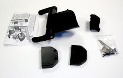
D&D Technologies USA Inc., is introducing the Z*LOKK, a double-sided lever handle magnetic gate lock. The Z*LOKK is operated by a magnet and metal rod locking mechanism. The magnetic locking mechanism requires no batteries or power source. The levers require only 30 degrees of rotation to unlatch the locking mechanism. The Z*LOKK locks can simultaneously open, unlock or lock the gate from either side of the fence. It can be left in the unlocked or locked position. The Z*LOKK is self-latching, even when in the locked position.
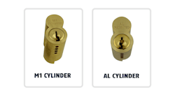
The outside and inside levers are equipped with six-pin tumbler key-in-knob lock cylinders having the KW1 keyway. The lock cylinders can be rekeyed or replaced to accommodate the customer's requirements.
The body of the Z*LOKK mounts onto three sides of the gate frame. This gate lock has been designed to be installed onto wood, metal, or plastic square tube gates and fence posts. The Z*LOKK is non-handed, meaning it can be installed onto left-hand or right-hand hinged gates and fence posts. The Z*LOKK is constructed of engineering polymers and stainless steel components.
Model ZL1-K fits most gate frames from 1 inch to 1-5/8 inches. Model ZL2-K is designed for large metal gate frames from 1-3/4 to 2-1/2 inches.
For the purpose of this article, we will install and rekey a Z*LOKK. The lock will be mounted onto a 2-1/2" square metal gate frame and fence post. The Z*LOKK requires a minimum allowable gap between the fence post and gate of 3/8". The maximum distance between post and gate is 1".
To install the Z*LOKK:
Step 1. Determine the height for installing the Z*LOKK.
Step 2. With its face cover removed, place the Z*LOKK onto the gate frame.
Step 3. Locate the four Phillips head mounting screw holes. Two holes are on the face of the frame and two are on the edge.
Suggestion: Although self-drilling/self-tapping screws are provided, it is a good idea to drill pilot holes when mounting the Z*LOKK onto steel gate frame and fence post. The recommended size for the pilot holes is 1/16"- 3/32" diameter.
Step 4. Mount the Z*LOKK level to ensure the locking mechanism will properly operate. Secure the lock to the gate frame using the four provided screws.
Step 5. Carefully slide the face cover onto the lock. The face cover must be slid straight onto the body using the guiding grooves for proper positioning.
Step 6. Install the two 3-inch screws that secure the face cover to the chassis. Start both screws before tightening. Make sure the cover slides tight against the gate frame.
Step 7. Mark the location for the mounting screw that secures the keeper (striker) onto the fence post. Use the ridge of the face cover to determine the centerline for the keeper.
Step 8. Place the keeper onto the fence post and start the mounting screw. Snug, but do not tighten this screw, as the keeper position may need adjustment. The keeper has elongated screw holes to provide the ability to adjust its position vertically up to 1/2 inch.
Step 9. Install the two screws through the edge of the keeper. Snug, but do not tighten these screws.
Step 10. Adjust the horizontal position of the keeper towards the fence post using the adjustment screw. The keeper must be adjusted to the stop for the gate to close and the lock to latch.
Step 11. Adjust the vertical position of the keeper, making sure it is centered within the face cover. The gate must close smoothly and latch.
Step 12. Tighten the two screws to secure the keeper onto the edge side of the fence post.
Step 13. Adjust the keeper forward to uncover the face screw.
Step 14. Tighten the face screw.
Step 15. Once the three screws have been tightened, adjust the position of the keeper to the stop. Test to be certain the gate closes and the lock latches.
Removing/Recombinating Cylinders
The lock cylinders in the outside and inside levers can be removed and recombinated or replaced to accommodate the end user's requirements. Note that the inside lock cylinder has a much longer tailpiece than the outside lock cylinder.
To remove the lock cylinder from the exterior lever:
Step 1. Remove the lock from the gate frame.
Step 2. Remove the two 3-inch screws in order to remove the face cover.
Step 3. Remove the face cover from the lock.
Step 4. Pull the ring stopper off the lever spindle in the face cover.
Step 5. Remove the handle clip beneath the ring stopper.
Step 6. Lift off the lever assembly.
Step 7. Remove the two Phillips head screws securing the lock cylinder in the lever.
Step 8. Slide the lock cylinder out of the lever and service as necessary.
To remove the lock cylinder from the interior lever:
Step 1. Remove the two Phillips head screws securing the cover onto the interior side of the lock chassis.
Step 2. Lift off the cover.
Step 3. With the face cover removed; unscrew the Phillips head screw securing the lever assembly.
Step 4. Lift off the clip.
Step 5. Pull up on the lever to disengage it from the chassis.
Step 6. While pulling up, pull out on the lever, sliding it out of the chassis.
Step 7. Remove the two screws securing the lock cylinder in the lever.
Step 8. Slide the lock cylinder out of the lever and service as necessary.
Reassemble in reverse order.
The Z*LOKK locks provide up to 1/2 inch of vertical and 1/2 inch of horizontal adjustment. If movement of the gate or fence occurs later, a simple adjustment will normally correct the alignment problem.
As with all D&D Technologies products, the Z*LOKK Magnetic Gate Lock comes with a limited lifetime warranty. The company also offers an interesting selection of other gate, storefront door, toolbox and specialty products.
Gate security has always been a challenge. While padlocks and welded boxes are one answer, the ability to offer a more convenient and secure product without the need for cutting, welding or gate modification is well-received by the locksmith and security professional.
For more information, contact your favorite locksmith distributor or D&D Technologies USA Inc., phone (800) 716-0888 or web site www.ddtechglobal.com.


