The doors are located in the corridors of a transportation complex where dramatic changes in air pressure cause doors to slam, closers to fail and door locks to vibrate so much that their case screws loosen and sometimes fracture. As a result, the components disengage, often resulting in mortise lock failure.
Rubber gaskets and screw adhesives failed to resolve this problem. Then the locksmiths decided to convert two of the mortise locks to cylindrical lock door prep for the SARGENT T-Zone locks. Each lock conversion door prep required two face (Remodeler) plates, a full opening ANSI strike plate and a filler plate for the door edge. A decision was made to use Don-Jo Mfg. parts for this installation.
The Remodeler plates are flat, 3-1/2" by 9", manufactured of stainless steel with an opening to accommodate a cylindrical lock in the center. For this installation, these plates are large enough to cover the mortise lock openings. The offset filler plate provides two choices for locating the 2-1/8" cross bore. This increases the likelihood of finding metal for the hole saw pilot bit. In addition, for some doors, offsetting the lock and latch may limit the amount of reinforcement that must be removed.
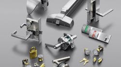
The SARGENT T-Zone is an ANSI Grade 1 bored-in cylindrical lever lock designed to fit in a standard 161 door prep, operating without thru-bolting. The non-handed T-Zone lever lock incorporates interlocking construction, having the latch assembly installed into the lock body (bearing assembly). Because of the interlocking construction, the SARGENT T-Zone requires only 45- degree lever rotation to fully retract the latch.
Note: The T-Zone for this installation was configured for a Best-Falcon interchangeable core. This T-Zone will accommodate a six- or seven-pin core.
The SARGENT T-Zone lever lockset has a cast stainless steel bearing assembly, latch assembly head, and sleeves. The levers are manufactured of solid zinc die cast. The T-Zone lock's standard configuration is a 2-3/4" backset into 1-3/4" to 2" thick doors. The T-Zone locksets can be ordered for 2-1/4" to 2-1/2" thick doors. This lever lock comes with a 1/2" throw stainless steel latch bolt. The front of the latch bolt is self-adjusting up to a 1/8" bevel to accommodate the door edge. For pair of doors, a 3/4" throw latch bolt is available.
To maintain an at-rest horizontal lever position, the bearing assembly has four torsion springs. To accommodate new construction and retrofit applications, the T-Zone is available with three sizes of roses: 2-3/4" and 3-1/2" diameter and 3-1/8" square. The 3-1/2" diameter rose is designed to cover existing door prep that has thru-bolting.
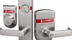
For this installation, the T-Zone lever lockset was ordered in the storeroom function, configured for Arrow/Best/Falcon Interchangeable Cores, with the 3-1/2" diameter roses.
The door into which the T-Zone was installed contains mortise pocket reinforcement. For this door, the reinforcements were steel plates forming the pocket and lock support clips to strengthen the door around the mortise lock body and keep the mortise lock body centered in the door cavity.
IMPORTANT: When drilling through a heavy-gauge hollow metal door or reinforcement using a hole saw, drill at a speed between 500 and 600 rpm. Should the hole saw jam, a 500 to 600 rpm drill motor will probably cause minimal damage, whereas a 1,500 rpm or faster drill motor could result in a battered if not broken wrist.
When drilling, spray a lubricant occasionally to keep bit cool. This increases cutter longevity, and improves the cut.
T-Zone Disassembly
For this article, the SARGENT T-Zone lever lockset was installed into a hollow metal door prepped for a mortise lock. The T-Zone lockset requires a 2-1/8" cross bore with a 1 inch edge bore. The T-Zone lever lockset comes partially assembled, and must be disassembled prior to install into the door.
Step 1. Unscrew the inside collar and remove the inside sleeve from the bearing assembly.
Step 2. From the outside of the bearing assembly, fully depress the aligning pin. The aligning pin must be fully depressed in order to remove the outside sleeve.
Step 3. Unscrew the outside collar and remove the outside sleeve from the bearing assembly.
Step 4. Slide the aligning pin out of the bearing assembly. The align pin serves two purposes -- retaining the latch bolt assembly and the outer sleeve.
Step 5. Slide the latch bolt assembly out of the bearing assembly. The T-Zone is disassembled, ready for installation.
Retrofitting The Door
The door must be retrofit from a mortise lock configuration to accommodate the T-Zone cylindrical lock configuration, which requires a 2-1/8" cross bore opening at the 2-3/4" backset. The Don-Jo Remodeler plates will cover the existing mortise lock hardware openings. The filler plate will convert the mortise pocket opening to accommodate the latch bolt assembly.
Step 1. Position the filler plate into the mortise pocket opening. Using the latch bolt assembly as a guide, determine the best location for the 2-1/8" diameter cross bore opening at the 2-3/4" backset. Avoid the lock support clips if possible.
Remember: The filler plate latch bolt location is offset, which means it can be located in one of two positions; higher or lower on the door.
Step 2. Mount the filler plate into the edge of the door using the two Phillips head screws.
Step 3. Mark the center for the 2-1/8" diameter cross bore opening. Use the center of the latch bolt opening in the plate.
Step 4. Use a 2-1/8" diameter hole saw to carefully drill through the door skin and the reinforcement plate.
Step 5. Drill through each door face from the outside to ensure an accurate cross bore opening. Remove any burrs using a file.
Step 6. Insert the bearing assembly into the door, making sure it slides freely and can be rotated. Remove bearing assembly and make any modifications necessary.
Step 7. Mount the filler plate into the door edge using the two black screws and the large Phillips head screw driver. Do not tighten the screws.
Step 8. Remove the mortise strike plate and install the replacement strike plate.
Installing the Lock
The door has been configured to accommodate the T-Zone retrofit. Install the lock:
Step 1. Insert the bearing assembly into the door with the opening for the latch assembly facing the filler plate.
Step 2. Slide the latch assembly into the bearing assembly. Make sure the latch seats within the bearing assembly.
Step 3. Insert the aligning pin into bearing assembly from the secured (outside) side of the lock. If necessary, slightly rotate the bearing assembly to accommodate the latch bolt assembly. Make sure the aligning pin slides completely into the bearing assembly cutout.
The alignment pin performs two functions. First, it locates/secures the latch assembly. Second, it eliminates unauthorized access by removing the outside sleeve.
Step 4. Start the two Phillips head screws to secure the latch bolt assembly into the filler plate.
Step 5. Install the outside sleeve onto the bearing assembly with the lever retaining dimple facing toward the latch.
Since a Storeroom function lock is being installed, the red outer sleeve driver tip is must match-up prior to assembly. The locking piece must be in the unlocked position prior to assembly. To unlock, insert a flat blade screwdriver into the slotted cam opposite the driver tip and rotate until the locking piece is towards the center of the outside sleeve.
Step 6. Thread the outside sleeve collar onto the bearing assembly. Tighten until there is a notch in the collar directly above the alignment pin. Test the operation using a flat blade screwdriver as described above.
Step 7. Insert the inside sleeve into the bearing assembly with the dimple facing toward the latch.
Step 8. Thread the inside sleeve collar onto the bearing assembly. As the collar is tightened, the alignment pin will slide into the notch in the outside collar. This locks the outside sleeve collar in place, preventing removal of the outside lever and sleeve from the exterior side of the door.
Step 10. Place the Don-Jo Remodeler plate onto the outside face of the door.
Step 11. Depress the lever catch button and slide the outside rose onto the outer sleeve. Thread the outside rose onto the collar. Make sure the tabs on the rose plates align with the cut-outs in each side of the bearing assembly. Do not tighten the rose.
Step 12. Adjust the position of the Remodeler plate using a level.
Step 13. Install one flange head Tek screw to secure the Remodeler plate.
Step 14. Tighten the outside rose using the supplied installation wrench.
Step 15. Install the three remaining flange head Tek screws through the Remodeler plate.
Repeat Steps 10-15, installing the Remodeler plate onto the inside of the door. The only difference is there is no lever catch on the inside sleeve. When completed, continue with Step 16.
Step 16. Mount the inside lever onto the inner sleeve. Install a set screw into the lever using the 1/8" hex wrench. The hex setscrew secures the lever to the inner sleeve. Test the operation of the inside lever.
Step 17. Depress the lever catch button and slide the outside lever onto the outer sleeve. Test the operation of the outside lever.
Note: If the lever catch button will not depress, insert a straight-slot screwdriver through the outside lever into the cylinder tail piece slot and rotate 45 degrees.
Step 18. Slide the tail piece into the rear of the core. The tailpiece is necessary for the core to operate the lock mechanism.
Step 19. Insert the control key into the core and retract the lug.
Step 20. Slide the core into the outside lever. Reverse rotation of the control key and remove. Test the operation of the T-Zone lock using an operating key.
Step 21. Tighten the two screws securing the latch bolt assembly. Check the operation.
The SARGENT T-Zone is available in 17 configurations and nine architectural grade finishes. For custom applications or colors, consult the factory.