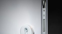
Narrow stile doors are everywhere. These glass doors with a narrow aluminum frame are used on storefronts in freestanding buildings, strip malls and on a variety of other door openings. Standard security options include: projection deadbolts, flip-up deadbolts, hook bolts and latching locks. Outer control is usually by key and inner control can be by key or thumb turn for deadbolts and by thumb turn, lever or push paddle for latching locks. There have been limited options for basic mechanical push button controls for these locks.
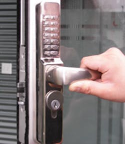
A new solution is the Codelocks 0465L mechanical push button lock, designed to be used with Adams Rite style latching locks. (Photo 1) One unique feature of the Codelocks Narrow Stile Mechanical Pushbutton Lock is by rotating the override key 360 degrees, the mechanical code is made invalid. This is an instantaneous method for locking out those individuals who have only the code. Rotating the override key in the opposite direction re-activates the code.
Codelocks, a multi-national company founded in 1990 in the United Kingdom, produces a wide variety of mechanical and piezo-electric door locks for commercial and residential use worldwide. The Southern California distribution center – opened in 2004 - supplies distributors throughout North and South America.
Four models of this lock are available: 0460 / 0465 / 0470 / 0475. Model 0460, shown in the article, is a narrow stile lock case with a threaded mortise cylinder for key override. Model 0465 is a narrow stile lock case with a threaded mortise cylinder for key override with a passage function. Models 0470 and 0475 mimic the previous models with the exception that they are supplied with a Euro-style profile cylinder in place of the threaded mortise cylinder. Model numbers with an 'L' suffix indicate a lever handle while the 'K' suffix denotes a knob style model.
The four models mentioned above are all designed to work with latching type locks and use levers or knobs to achieve that action. Additional models will be released in the near future, which will work with flip-up and hook bolts.
Each of the four lock models is equipped with a pushbutton code front housing with a threaded mortise cylinder (or profile cylinder). (Photo 6)
Two 'C' keyway keys were supplied with this lock. An inner housing, two neoprene seals, two levers, two spindles, two compression springs and a cam plug are also supplied. The lock is shipped prepared for a right-hand installation but the gear ring for left-hand operation is included.
Mounting bolts, a spindle set, compression springs, an Allen wrench and two spare tumblers are sent in a bag with a small pair of tweezers. A code card, drilling template, installation, code changing and operating instructions complete the package.
The code chamber on models 0460 and 0470 consists of 13 buttons from which the code is selected. A 14th button, marked 'C', is used to clear the chamber after an incorrect entry, and is always used as the first digit of a given code. This assures that the chamber is cleared before any code string is entered. The black dot on the "Y" button signifies that this lock has the passage function option. (Photo 8)
This mechanical entry-level lock offers only one working code at a time. Each button may be used only once in a code. The code can be entered in any order or sequence. In other words, code 1234 can also be entered as 4321, 2413, 4132, etc.
With 13 buttons, a total of 8,191 different codes are available, any of which can be entered in any sequence. This total includes codes with "C' plus one digit through "C" plus 13 digits. Most people will set code lengths of "C" plus four to seven digits. The lock is factory set with a randomly selected five-digit code prefaced by the "C" button. Our factory code is C3467X. (Photo 7)
Codes can be changed as often as necessary to any other five-digit code. Increasing or decreasing the number of digits in a code requires adding or removing spare tumblers.
After clearing the chamber, remove the two red screws and carefully lift off the code plate, verifying that all 14 springs are in position. (Photo 11)
Red tipped tumblers are active code tumblers and blue tipped tumblers are non-code tumblers. (Photo 10) The "C" tumbler has no color.
By holding down the "C" button and using the tweezers to move the positions of red and blue tumblers, you can change the code setting. It is essential to keep the "C" button depressed when removing or replacing tumblers. The square notches of all tumblers must face outward with the colored tips on top. A diagram is supplied with the instructions.
After the tumblers are in position, replace the code chamber plate and two red screws.
Check the operation of the new code before installing the lock.
Prior to installing the lock, the door must be prepped. Our door had an existing latching lock with a paddle. After removing the paddle (Photo 2), the lock was removed and the two threaded posts were removed from the door. (Photo 3)
The template was used to mark the positions of the thru-bolt holes. After drilling the holes (Photo 4) the Adams Rite lock is replaced in the door. (Photo 5)
The lock housing is then checked for the proper handing. Changing the handing is a simple procedure. Remove the back plate and remove the gear ring from the lock. (Photo 12)
The locks are supplied with the gear train set to work on right hand doors. If the spindle hub is flipped over and the left gear ring installed, it will operate with a left hand door. Note the alignment marks. (Photo 13)
The proper spindle is then selected to work with the door handing. (Photo 14) This spindle works in conjunction with the Adams Rite 4580 cam disc. A blue or red tip on the spindle matches the color-coding on the gear ring. The chosen spindle is installed with the compression spring in the outer code housing. (Photo 15) The other spindle is used on the inside knob or lever.
Note: Before installation, the locating pins must be removed from the cam disc. Use a pair of pliers to remove the pins. They are not needed and will interfere with the lock housings. (Photo 16)
Install the levers on the inner and outer housing hubs with the supplied Allen screws and wrench. (Photo 17) Size the segmented mounting screws to accommodate door thickness. Break off the excess length. Use the segmented mounting screws to secure the lock. (Photo 18) Before closing the door, enter the code and verify that the latch fully retracts and releases form the outside. Also verify proper operation of the inside lever.
Enter the set code (in any sequence), starting with the "C" button to clear the chamber. We entered C-3-4-6-7-X. (Photo 19) The outer lever is then rotated to withdraw the latch. (Photo 20)
Turning the override key in one direction will momentarily retract the latch. Turning the key 360 degrees in the opposite direction will render the valid code inactive. Reversing the above procedure will reactivate the code.
To put the lock into passage function, enter the correct code followed by the "Y" button. The lever will now retract the latch without requiring the entry of a code. To reset the lock to code entry mode, press the "Y" button followed by the "C" button.
This simple lock is an affordable alternative to electronic keypads, electric strikes, magnetic locks and other storefront door security measures. In many strip malls and small businesses, it will allow controlled entry with a valid code. Model 0465L adds a handy option with the settable passage function.
This lock requires no maintenance of the working parts. The heavy-duty components of this lock should hold up under repeated usage in most any application.
For more information contact your local locksmith distributor or contact Codelocks at www.codelocks.com
