I was invited to observe the installation of Securitron Maglock Digital Keypad and Touch Sense Bars on a pair of interior doors at a medical facility. To our advantage, the section of building into which the access control system was being installed was equipped with a drop ceiling. However, some of the walls were poured concrete, while other walls were stick construction with lathe and plaster.
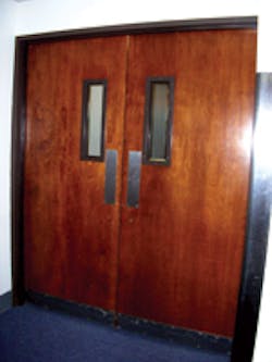
The medical facility wanted to control access through a pair of outswinging doors that separated the reception/waiting area from the offices and surgery areas. The two wooden doors are mounted onto a hollow metal frame. On one side of the pair of doors are offices. On the other side are restrooms. However, in the secured area, within close proximity to the doors, is a supply storage/janitorial/electrical room, where the plug-in transformer, power supply and the DK26 circuit board are to be installed.
IMPORTANT: To simplify the installation, Securitron provided a point-to-point wiring diagram. In addition, they provide "live person" technical support when requested.
For this installation, two 1200 pound M68LS Securitron Magnalocks were installed. These automatic dual voltage (12/24VDC) M68 Series Magnalocks are bracket mounted and equipped with a built-in wire access chamber. The current draw is 300-325mA (including options) at 12VDC, and 150-175mA (including options) at 24VDC. For this installation, the M68 Series Magnalocks were ordered with LED and Senstat.
The Senstat option is a Form 'C' isolated contact that senses when the lock and the strike plate are in proper alignment. Proper alignment positively indicates that the door is secure. This option can be connected to the access control or an alarm system to notify when the door is not secure.
KEYPAD SYSTEM
A Securitron DK-26 Digital Keypad System provides controlled access through the doors. The DK-26 is manufactured from cast stainless steel, and equipped with EPDM buttons. This two-component system incorporates a true 10-digit keypad with beeper and three LEDs and a separate CPU board in an enclosure. The DK-26 has a DPDT 5A maximum relay. The current draw is 160mA maximum at 12VDC, and 190mA maximum at 24VDC. For convenience, the keypad is equipped with a 16-foot 12 conductor, 22 gauge cable.
NOTE: The DK-26 is a tamper resistant keypad that, according to Securitron, will not provide access even if destroyed or removed from its mounting position.
There are two programming choices for the DK-26 Digital Keypad System; the single "Hard Code" and the Keypad Changeable. The "Hard Code" enables access using a single two- to seven-digit code. A "Hard Code" is normally used for traffic control applications where one code is used by all employees.
Keypad changeable programming enables access using up to 59 different, two- to seven-digit codes (expandable to 119). There are two types of keypad changeable programming codes: the Program Code and the User Codes. The Program Code acts as the password that adds, deletes, or changes User Codes. The Program code is five to seven digits in length. The User Codes are two to seven digits in length.
Since the DK-26 is designed to accept multiple codes of different lengths, the software will reject duplicate codes and code subsets. For example, there is a programmed User Code that is 1234567. If code 34567 is attempted to be programmed, the software will reject it.
To ensure accurate programming, always test the "Hard Code" or the Keypad Changeable Programming Codes, and the User Codes once programming has been completed. For this installation, the "Hard Code" or the User Codes should release the magnet. The Programming Codes should cause the yellow LED to flash rapidly, indicating the system is in programming mode.
EXIT DEVICE
The Securitron Touch Sense Bar, model TSB-3, is an exit device for doors secured by magnetic locks. The Touch Sense Bar is not mechanical; it operates by sensing the electricity expended by the hand(s) when it contacts the aluminum bar. When the bar is touched, a relay in the sensor is tripped, cutting power to the magnetic lock(s). The sensitivity of the bar is adjustable using the switch on the rear of the bar at the hinge side of the door. In addition, the switch has a push button that when pressed, trips the relay, cutting power to the magnetic lock(s). The Touch Sense Bar can be cut to accommodate varying door widths.
POWER SUPPLY
The Securitron PM linear power supply provides regulated 1 Amp DC power using a plug-in transformer and a circuit board housed in a steel enclosure. The PM power supplies include AC fusing, DC output, automatic circuit breakers, battery charging capability and fire alarm compatibility. The PM-24 provides 24 volts, 1 Amp capacity.
Note: Always comply with applicable building codes. Check with our local authority having jurisdiction (LAHJ) before installing electronic lock systems.
The installation proceeded with determining the locations for the plug-in transformer, power supply enclosure and DK-26 CPU board enclosure. Within the secured area, in close proximity to the pair of doors. is a supply storage/janitorial/electric room, where the plug-in transformer and the two enclosures were installed. The enclosures were mounted close to the ceiling of the room and the plug-in transformer was plugged in to a nearby wall outlet.
The DK-26 keypad was installed onto the left wall (facing the doors) by drilling a 5/8" diameter hole and running the sixteen feet of cable up to the top of the wall.
To pull the DK-26 cable; a two-inch diameter hole was drilled through the top plate directly above the DK-26 cable hole in the wall. A length of stranded wire was lowered through the two-inch hole and a piece of bent wire fished the cable out of the 5/8-inch diameter hole in the wall. The DK-26 cable was tied to the stranded wire, and pull up through the two-inch hole.
The DK-26 was then mounted onto the wall using the two supplied screws.
A decision was made to locate each Touch Sense Bar at 1-3/8" in from both edges of the door. The two bars were cut to size to accommodate the doors using a hacksaw. The bars were cut from the end opposite the circuit board. The bars were located, leveled, and installed at approximately 41" above the finished floor with the circuit boards at the hinge edges of the two doors. Because the end pieces of the Touch Sense Bars are plastic, it provides a cleaner installation for one end of the door cord to exit the End Piece Cover instead of using the door cord end piece. To do this, the plastic end pieces were modified to accommodate one end of each stainless steel door cord. The other end of the door cord would be attached to the frame once the system was wired.
The plastic end pieces are made of two parts: end piece and the end piece cover. A 1/4" diameter hole was drilled through bottom of both pieces on the circuit board (hinge) side of bar. The hole was enlarged slightly to provide sufficient room for the stainless steel door cord. The end piece cover was then removed and a slot slightly larger than the diameter of the door cord was cut from the edge to the hole in the end piece. This slot would allow the door cord to be mounted onto the end piece cover and still be slid in place onto the bar.
Once the bars were installed onto the doors, the touch sense bar's wiring would be run through the door cord. The door cord would then be fed through the opening in the end piece cover. An "E" clip would be positioned at just about the end of the door cord, stopping it from being removed. The wiring was connected and the end piece cover was slid in place onto the end piece. The screws were installed. The door cords were pulled tight against the end piece cover and a second "E" clip was installed against the cover from the outside. With the two "E" clips in place, the door cord would not accidentally come loose.
MAG LOCK
The bracket-mounted M68LS Magnalocks are supplied with a template. Use the template to determine the mounting locations for the magnets. The magnetic lock brackets were installed onto the header portion of the metal frame using blind nuts. Holes were drilled to accommodate the blind nuts as well as for the wiring. The two blind nut bracket holes provide adjustment for the magnet to slide forward or back in order to align with the strike plate. Once in position, three additional machine screws are installed to secure the bracket in place.
To secure the magnet onto the mounting bracket once the wiring has been completed, install four hex set screws, one in each corner. Use the provided hex wrench to loosen the screws and slide the bracket off the magnalock.
The strike plates were mounted onto the wood doors using sex bolts. Following the punch marks, three holes were drilled into the wood door. Two holes were drilled for the strike roll pin bushings. One hole was drilled through the door for the socket flat head screw. From the back side of the door, this hole was enlarged to accommodate the sex bolt.
Two roll pins are first driven part way into the two smaller openings in the strike plate. The extending portions of the roll pins slide into the strike roll pin bushings that are mounted into the door. The purpose of the roll pins is to keep the strike plate in alignment with the face of the magnet. Three rubber bushings are included with the M68 Series Magnalocks. Their purpose is to position the strike plate within contact range of the magnetic lock face. Depending upon the specific installation; one, two or three rubber bushings are slid onto the bolt behind the strike plate. Trial and error is used to determine the number of bushings. Then the strike plate is mounted onto the door. For this installation, two rubber bushings were needed to properly align the strike plate to the face of the magnetic lock.
WIRING
At this point in the installation, the wiring was run from the power supply to the CPU and to the Touch Sense Bars and the magnetic locks. The keypad cable was connected to the CPU. Once all of the wiring had been run and checked, the plug-in transformer was powered and the system ready for programming and testing. Note: As can be seen by the point-to-point wiring diagram, activation of either touch sense bar will release both magnets.
For general consideration, if the power supply is less than 50 feet from the hardware, use 20-gauge stranded cable. If the wire run is more than 50 feet, contact the hardware manufacturer for wire gauge.
An additional wiring procedure was done to increase the reliability of this single fixed code installation. Install a wire jumper between terminal SRC and terminal UCD. This wiring eliminates any User Code from unlocking the door.
PROGRAMMING
For this installation, management wanted a "Hard Code" for traffic control. To program the "Hard Code:
Step 1. Power the system. Confirm steady yellow LED. In the absence of a steady yellow LED, the unit has already been programmed with one or more codes. All codes must be erased before the DK-26 can be operated with a single code.
Step 2. Press the "Hard Code" button on the CPU for one second (see Drawing)
Step 3. Confirm slow flashing yellow LED.
Step 4. Within 30 seconds of pressing "Hard Code" button, enter a two- to seven-digit code.
Step 5. End the programming session by pressing the bell button or wait five seconds. Note two red LED flashes for confirmation.
Step 6. Enter the two- to seven-digit code. Power should be cut to the magnet and the door should be able to be opened.
Test the operation of the access control system. Enter the "Hard Code." Both doors should unlock. From the secure area, press on each of the Touch Sense Bars and push open the doors. Check to see that the LED on the rear of each magnet will be red when the lock is powered and secure. The LED will indicate green when the lock is powered but not secure.
When the access control system is fully operational, place the decal over the bottom screw hole in the DK-26 keypad.
Installing an access control system using one manufacturer's components can be very comforting for those locksmiths who are not completely comfortable with installing electronic components. Should there be any questions, one telephone call will usually solve any problems. Securitron provided a point-to-point wiring diagram to help speed the installation.
Finally, the Securitron MagnaCare Lifetime Replacement Warranty is all-inclusive. If something is wrong with a Securitron product you are installing, they will replace it. The exception is batteries and custom orders.
SHOPPING LIST
The shopping list for the above installation included:
- Two DK-26SS - Digital Key system Narrow Stainless steel
- Two M68LS - 1200 pound Maglock with LED and Senstat
- Two TSB-3CL* - 36 inch Touch Sense Bar
- PM-24-1 - 24 volt power supply
- Assorted cables for wiring the components (Cable lengths and gauges vary depending upon the specific installation)
* A Door Loop is included with each Touch Sense Bar.
For more information, contact your local locksmith wholesaler or Securitron Magnalock Corp., 550 Vista Blvd. Sparks, NV 89434. Telephone: 775-355-5625 OR 800-MAGLOCK. Fax: 775-355-5633. Website: www.Securitron.com.


