Commercial and institutional locksmiths will find themselves working on construction sites. Whether they are working for a construction company or owner, they may be furnishing or installing hardware specified by a set of plans.
Construction documents are also referred to as building, construction or working plans. Sometimes they are loosely referred to as “blueprints.” They consist of set of plans, details, specifications, worksheets, schedules, statements and certificates.
Locksmiths who intend to concentrate on new construction hardware should attend specialized courses (or series of courses) that cover all aspects of construction documents.
Locksmiths who only occasionally deal with new construction should also gain enough education to at least know what to look for in the construction documents and how to interpret them.
If you don’t know what to look for or how to find it, the set of construction documents will be especially intimidating. The documents are for all trades so most of it will not pertain to the locksmith.
By mastering the movement from door schedule; to detail; to floor plan; and then elevation, all the information that is necessary to order and install hardware can be acquired.
These are parts of the construction documents that locksmiths are concerned with.
Locksmiths who install electric locks or access devices will also need to review the electrical plans and specifications but these are the types of locksmiths that are better served acquiring a comprehensive understanding of construction documents through advanced courses.
To apply these basics, locksmiths should ask construction companies in their area for old construction documents and then practice the mentioned procedures.
Bring Your Camera
Prepare by bringing your “tape measure. If you don’t already have one, consider purchasing a digital camera. The digital camera has become as important to the locksmith as a tape measure is to a carpenter. When reviewing construction documents; always bring your “tape measure” (digital camera). I use it in place of a clipboard as it is faster and more accurate at making notes.
The images in this article were cropped from the digital pictures taken from a set of construction documents.
Always set the digital camera at the highest possible resolution and expect to take flash shots at the macro setting. Take many shots.
On the Title Sheet, snap pictures of the symbols, abbreviations. Snap a picture of the project number and any addresses that refer to the different construction contacts including the architectural firm, the construction company, and the customer.
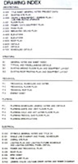
Drawing Index
The first page of the construction documents should always be the Title Sheet. It includes: general notes, symbols and materials, abbreviations and a drawing index.
The locksmith should become familiar with the different symbols and then use the drawing index to locate the parts of the control document that concern the task at hand.
The drawing index is grouped by page type. The floor plan; elevations; details; and schedules (not in that order) are usually found in the Architectural group.
Additionally, under the Structural group, there may be pertinent notes under the General Notes page.
The first page to navigate to is that page that displays the “door schedule.” In this case it would be “A-700 Schedules/Details.”
Door Schedule
Always start with the door schedule. All the information relating to the individual doors is cross-referenced here, including the name of the area in which the door serves; the area or room number; the frame type; the door type; the size of the door; the opening number (how the door is designated on the floor plan); the hardware type for the door; fire ratings; and remarks about the door.
Every door being installed or remodeled should appear as a line item in the door schedule.
The designation of the door is the opening number. An area may have more that one door serving it. For example, in Figure 2, there are two doors in the “WAITING AREA”. The area or room number for the waiting area is “400.” The first door is designated by the opening number of “400,” matching the area or room number. The second door is designated as “400a.” The “A” infers that it is the second door serving the area. If there were a third, is would have been designated “400B.”
From the door schedule, door “400a” has a door type of “DSV” and a frame type of “SOS.” The door is 36” wide and 84” tall. The hardware installed on the door is listed under the hardware specifications under set: “100.”
As you review the door hardware schedule, take a snapshot of the entire table.
When taking snapshots of documents: always try to be as perpendicular to the paper as possible so as to limit the amount of distortion that angles produce.
Taking pictures at high resolution will guarantee clarity when later zooming for details.
Hardware Sets
In this set of construction documents, the hardware specifications appear on the same page as the door schedule.
On larger projects, hardware specifications might appear in a separate book or catalog. When hardware specifications are in a book or catalog they will be found under “Division Eight Hardware.”
Hardware specifications under set: “100” indicate that a “pair-and-a-half” of standard 4-1/2”x4-1/2” butt hinges is used to fasten the door to the frame (CB179 4 1/2 x 4 1/2 652 ST). A Classroom lock secures the door (93K-7R14D83 PATD 626 BE) the door. The door is self-closing by having a closer installed (D-3551 P 689 RY). A wall bumper is installed to keep the lockset from hitting the door (1270CV 626 TR). Three door silencers are installed into the door frame to minimize the noise of the metal door hitting the metal frame (1229A TR).
Note: Handing of the hardware is not mentioned in the specifications and is left up to the hardware supplier.
At the bottom of the specifications is an important note: “List products are basis of design, equivalent products by approved manufacturers.” This tells the hardware supplier that if an equivalent product is going to be used it must first be authorized by the customer or customer’s agent (construction company or architect).
Sometimes a note that includes “or equivalent” or allows the hardware supplier to substitute products without authorization as long as the products being substituted are equivalent (i.e. Grade 1 lockset with Grade 1 lockset).
These particular construction documents do not include a means to determine which manufacturers are being used but the product numbers mentioned can be looked up on the Internet.
The person that specified the hardware in this set left a clue as to the manufacturers of each product. Refer to the last two letters in each product description: “BE”, “ST”, “RY”, and “TR”. These abbreviations (to the experienced) refer to: Best, Stanley, Ryobi, and Trimco.
If the locksmith is supplying the hardware and cannot find a product by its designation, the general contractor can help locate that information.
Door frame types
On the same page as the door schedule, there is a detail called “Door frame types.” (See Figure 3) Door “400a” in the door schedule referred to a door type “DSV”. Figure 3 reveals that this is a solid core door with a “fusion maple” veneer.
Notice that Figure 3 is an elevation. An elevation is a “flat” horizontal view of: a wall, a side of a building; or a detail. In this case the elevations show details of each door displayed in Figure 3. The diagonal dashed lines designate a swinging door.
The elevations also help specify where lites and vents will be mounted onto doors.
Head, jamb, and sill details
Again from the door schedule door “400a” has a frame type “SOS.”
Figure 5 is a combination head and jamb detail. Head details are horizontal cross-sections of the head of the door. Jamb details are vertical (looking down) cross-sections of the jamb.
A combination head and jamb detail infer that the there is nothing to learn from displaying separate details.
In Figure 5, how the door is mounted to the jamb and how the jamb is mounted to the wall is detailed. Snap on trim is featured as Timely jambs are being installed.
A quick glance at the “Code to Door Schedule” defines “SOS” as a “Snap-on-steel, pre-finished” door.
Another useful detail is in Figure 7. These elevations note the height in which the locking hardware is mounted from the finished floor.
Scaling
If there is a discrepancy where a measurement seems wrong, a ruler can be used to verify the details as everything is drawn to scale.
As plans are photographed, scanned, or plotted, the overall drawings might be scaled down.
Actual scales are drawn onto plans for this purpose. In the case of a reduced or expanded copy, the scale can be measured and a ratio can determine the intended measurement.
For example, a scale was drawn indicating that 3 inches equals a foot. The scale should be exactly 3 inches long. If the scale is measure and it is 2.5 inches long, a ratio can be made so that measurements come out right. The left side of the ratio would always be 2.5 divided by 3.
A line that is measured as 2 inches on the drawing is drawn to the same scale. The right side of the ratio would be 2 divided by X.
The ratio equation would be 2.5÷3 = 2÷x
The solve for X is: 2.4
Since each inch equals 4 inches (the scale is 3” equals a foot), then 2.4 inches would equal 9.6 inches.
Working with floor plans and elevations
In Figure 8, on the partial floor plan, the door “400a” is highlighted.
Here it is easy to see why a wall bumper was specified in Set 100. For the first time, the handing of the door can be determined. When standing outside of the room, the hinges are on the left side so the door is “left-handed.” Because the door opens inward the bevel is standard.
Note that each door on the floor plan has an opening number.
The term seems awkward but it is more accurate than if we use “door number.” If an opening accommodated either a set of double doors or a set of double doors that swung in different directions and had a mullion between them, then it would be hard to designate the doors with one number. The opening number is easier to apply.
Floor plans offer vertical views (looking down) and elevations offer horizontal views (looking across).
Egress Plans
Modern construction documents include egress plans.
Where egress plans are not helpful as far as determining opening numbers or elevation symbols, they are helpful in determining where exit hardware needs to be installed.


