Warranty: 3 Years
Time to Install: 45 minutes to one hour
Tools: 10-24 tap, 1/4-20 tap, drill bits, tools to adjust door closer, drill motor, 5/64" hex wrench
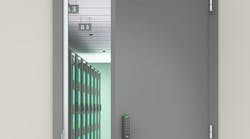
I was invited to the retrofit of a Von Duprin 99 Series Exit Device using the new XP98/XP99 Center Case on one of a pair of entrance doors leading into a gymnasium. There had been an attempted burglary in which one of the exit devices center cases was damaged.
Von Duprin had recently introduced the XP98/XP99 Rim Exit Device with the new patented center case design, a new two-piece latch bolt, heavy duty bracket, strike plates and hardened mounting hole guides for the center case. The operation of the XP98/XP99 has also been changed. The 98/99 push bar is directly linked to the latch bolt; pressing the push bar retracts the latch bolt. When the push bar is pressed, the internal locking mechanism of the XP98/XP99 is retracted, releasing the latch bolt. As the door is opened, the latch bolt pivots out of the way, enabling the door to be opened.
When the door is closed and dead latched, the two-piece latch bolt is in the rest position. If force is exerted onto the door, the latch bolt comes 90 degrees to the strike surface. According to Von Duprin, “The XP98/XP99 Rim Exit Devices meet ANSI/BHMA A156.3 Grade 1, and are UL listed.” In addition, “The XP98/XP99 has a static load force resistance of more than 2,000 pounds.”
To provide an alternative to replacing an entire 98/99 exit device when only the center case needs replacing, the XP 98/99 is available as a Center Case Retrofit, part number XP99-909-050676. The XP98/XP99 has been designed to match the footprint of the current 98/99 rim exit device. This enables this new center case to be installed onto an existing 98/99 exit device rail. The Von Duprin Center Case Retrofit contains the XP98/XP99 center case, case cover, XP bracket, push bar guide and a 909 strike package or a 954 strike package. Note: The old strikes including the 299, 299F and the 499F cannot be used with the XP98/XP99 exit device or center case.
There are retrofit limitations as the exit device mounted onto the gymnasium doors was manufactured during the time when Von Duprin used exposed rivets on the portion of the push bar that retracts into the mechanism case when the push bar is depressed. These early versions of the 98 and 99 Series exit devices cannot be used with the XP 98/99 Center Case retrofit.
Luckily, the locksmith had several Von Duprin 9947 Concealed Vertical Rod Devices in his service vehicle. Since many Von Duprin exit devices use interchangeable parts, we were able to use the push bar from a 9947 Exit Device to retrofit the XP98/XP99.
To retrofit the exit device into an XP98/XP99:
Step 1. Remove the cover from the center case.
Step 2. Remove the two Phillips head screws securing the bracket to the baseplate assembly.
Step 3. Slide the mechanism case away from the center case approximately five inches. This provides access to the two mounting screws and the retaining pin, which connects the mechanism to the latch release.
Step 4. Remove the two screws and the connecting pin.
Step 5. Remove the existing center case.
Step 6. Slide the XP center case onto the baseplate assembly.
Step 7. Install the pin. It may be necessary to adjust the assembly position to install the pin. Secure using the retaining ring.
Step 8. Install the two thread cutting mounting screws.
Next, determine if the push bar is equipped with plastic guides at each end. Remove the mechanism case completely to inspect both guides. If equipped, and the guides are in good condition continue with Step 9. If not, replace the plastic guides on each end of the push bar.
Step 9. Install the XP bracket onto the baseplate assembly. Check the latch function.
To check the auxiliary bolt, make sure it will slide into and spring out of the center case.
To check the latch bolt, depress the auxiliary bolt. With the auxiliary bolt depressed, try to move the latch bolt. It should not move.
With the auxiliary bolt depressed, press and hold the device push bar. The latch bolt should pivot in both directions.
The retrofit exit device is now ready to be installed onto the door. For this installation, the existing exit device and strike had to be removed. Remember: The existing strike is not compatible with the XP98/XP99 center case latch bolt. The position of the Master Cam and the lock slide must be determined. The purpose of the Master Cam is to time the exterior lock cylinder in order to be able to unlock the exit device.
Before installing the retrofit exit device onto the door, the master cam on the door side of the center case of the exit device being removed must conform to the master cam on the retrofit. If the master cam is not on the door mounted exit device, then remove the master cam from the XP98/XP99 center case.
If there is exterior trim equipped with a night latch (NL) function lock cylinder, the Master Cam must be kept and aligned to accommodate the handing by determining the position of the lock slide. The lock slide on the removed center case is either up or down. Make sure the XP98/XP99 center case lock slide is aligned to match.
NOTE: If the Master Cam is not properly aligned, the exterior lock cylinder will not be able to release the latch bolt and open the door.
To install the retrofit exit device onto the door:
Step 1. Install the tailpiece guide into the Master Cam aligned with the configuration of the tailpiece (vertical or horizontal).
Step 2. Align the rim cylinder tailpiece to slide into tailpiece guide.
Step 3. Slide the center case against the face of the door.
Step 4. Install the center case mounting screws supplied with the retrofit kit.
Note: Because only two mounting screws were used to secure the center case of the exit device to the door, two additional holes had to be drilled and tapped for this installation. The two holes that had not been drilled were those used to secure the bracket and center case to the door. To drill and tap the holes, use a #25 drill bit and a 10-24 tap.
Step 5. Install two mounting screws supplied with the retrofit kit to properly secure the center case to the door.
Step 6. Install the end cap mounting bracket, making sure the rail is level.
Step 7. Install the end cap. Test the operation of the push bar and the trim lock cylinder.
To install the 909 strike:
Step 1. With the door closed, position the strike centered to the latch bolt on the mullion.
Step 2. Use a pencil and mark the top and bottom screw holes.
Step 3. Drill using a #7 bit and tap the holes to accommodate the 1/4-20 screws.
Step 4. Install the 909 strike. There was no need for the included spacer.
With the door open, test the operation of the exit device.
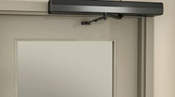
Make sure the door closer is in adjustment in order to close the door and latch the exit device.
Make sure the door can be opened from the exterior using the key to operate the trim.
Make sure pressing the push bar release the latch bolt.
Make sure the door will not open when pushing on the interior side of the door.
Make any necessary adjustments.
Step 5. Install the center case cover using the four supplied screws.
The Von Duprin XP98/XP99 rim exit devices and retrofit center case are designed for single and double doors with mullions. The exit devices are available in either three- or four-foot lengths. The XP98/XP99 functions are field selectable. They can be ordered with one of four dogging options: hex key, cylinder, special or less dogging. New options include alarm exit kit, monitoring switch(s) and double cylinder. The XP98/XP99 rim exit devices can be order fire rated which is UL Listed for A, B, C, D, or E fire labeled installations.
For more information, contact your local locksmith wholesaler or Von Duprin, 2720 Tobey Drive, Indianapolis, IN 46219. Telephone: 800-999-0408. Web Site: www.vonduprin.com.
Editor's Note: Photos that support this article will be available to view in a few days. Please visit again to more insight.