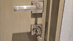
One of the latest trends to emerge in the security field is the ability to rekey a lock cylinder to a new combination without disassembly. The re-codeable lock shown here is made by Master Lock. According to our sources, this deadbolt version may be followed by other re-codeable lock types by Master Lock. An end-user may eventually have one key which would operate all the Master locks for their home plus any utility locks they may own.
News reports in October 2006 indicated that Strattec had developed a re-codeable lock system for use by Master Lock. The first result of that partnership is this Master re-codeable deadbolt.
Master Lock did not stop with only a re-codeable feature. The deadbolt has several other outstanding features. A hardened pin in the bolt unit deters sawing. The outer collar spins to stop wrench attacks. A top and bottom shield protects against attempts to bypass the bolt unit with an ice pick. Use of the popular KW1 keyway allows rekeying into many existing lock systems. An extra-large thumb turn aids handicapped persons in operating the lock.
Depth and spaces are identical to those used for Ilco/Jet KW1-type blanks. The lock is designed to use depth increments of .023 and depth number values of one through six. New sets of cut keys are available from Master Lock for rekeying purposes.
Locking security depends on a sidebar. In addition, a spring-loaded locking detent at the end of the cylinder plug also holds the plug in the locked position. This detent stops the plug from turning until a key is fully inserted. The detent deters someone either from trying to turn a partially inserted key or from attempting to pick the lock.
FAST FACTS
Some facts about the lock will help to clarify the operation:
1. Approximately one-third of the lock plug is cut away to accept the sidebar unit.
2. The sidebar unit contains five inner grooves to hold moveable blocks.
3. Tumblers have a ‘V’ notch on one side (similar to GM six-cut tumbler construction). All tumblers are identical and have the notch in the same location.
4. Moveable blocks form a connection between the sidebar unit and the notches in the tumblers. Each block contains sets of teeth. The distance between each tooth is .023. Each block contains a ‘V’ shaped projection which is used to interact with the tumbler notches.
5. A moveable rack also fits into the sidebar unit. The rack has arms which extend between each moveable block. Each arm contains teeth identical to the teeth in the moveable blocks.
Teeth in the moveable blocks are connected with teeth in the rack. Depending on which teeth are connected together, each block can be held at any one of the six possible depth positions.
The blocks are factory-set in the rack to form a contour pattern exactly the same as the cuts of the original key.
When a key is inserted into the plug, ‘V’ notches in the tumblers are held in the same contour pattern as the key cuts. Turning pressure on the key blank causes the beveled sidebar to move slightly inward. If the tumbler notches form the same pattern as the blocks held by the rack, each block projection will fit into a corresponding tumbler ‘V’ notch and the sidebar will be able to move fully inward to an unlocked position.
CHANGING COMBINATIONS
An operating key and a change tool must be available. Insert the key and rotate the plug 90 degrees clockwise. An access hole on the edge of the plug will now be at the top (12 o’clock) position. Insert a change tool into the access hole and press inward.
Note: Keep the plug in the rotated position and the change tool fully inserted at all times while completing the changing procedure.
You will notice a definite spring action when the change tool is fully seated. This spring action lifts the rack outward and away from the moveable blocks. The blocks are then disconnected from the rack, but they remain connected to the lock tumblers.
Remove the old operating key and insert a key with a new combination. As the new key is inserted, it will move both the tumblers and blocks into the new key combination contour.
Remove the change tool. As the change tool is removed, a spring in the housing presses the rack inward into the blocks, holding them in their new contour arrangement.
The final step is to turn the key counter-clockwise back to the vertical position. As the key is then retracted from the plug, ‘V’ notches on the tumblers press against projections on the blocks. This action moves the sidebar outward into the locked position.
The blocks are now held by the rack in the new key pattern configuration and any former operating keys will no longer operate.
For further information contact your local locksmith distributor or: Master Lock , telephone 800-308-9244 or web site www.masterlock.com.


