Door closers have been around for more than 120 years. The door closer was developed to close a door after someone who opened the door did not close it. I guess some things just don’t change. (For an update, see Door Closers 101: An Update.)
The basic door closer concept has not changed since the advent of the fluid operated, gear driven door closer. Previous designs incorporated piston mechanisms (pot/traditional closers) and a clock spring that would wind up as the door opened. The spring would unwind as the door closed. A shaft connected the piston to the spring. To control the speed of the unwinding spring, piston movement forced fluid through orifices in the cylinder. Many pot closers have two orifice holes in different positions. The first larger hole would permit faster movement (sweep speed). The second smaller hole, closer to the end of the travel, was designed to restrict fluid movement and slow the door during final closing (latch speed).
Note: Without control from the fluid and piston, the spring could unwind rapidly and the door would slam.
To gain the additional force needed to close and latch the door, closer manufacturers would set the spring under pressure before the unit was even installed. Locksmiths could easily add even more spring pressure using a claw wrench (provided by the manufacturer) when necessary (wind conditions, door issues, etc.). This pre-loading tightened the spring even more.
There is a reason for pre-loading door closer springs. Pre-loaded spring pressure ensures that a fully closed door will stay in the closed position and resist changes in air pressure or other conditions. Spring pre-loading also provides sufficient pressure to close and latch the door.
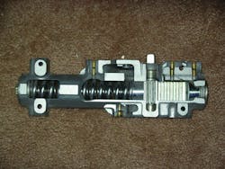
Today, most modern closers incorporate a compression spring (and sometimes a second spring within the main spring) along with a gear-driven spindle and piston. As the door is opened, the arm assembly rotates a geared spindle which drives a gear-driven piston backward and compresses the main spring. An automatic check valve opens allowing fluid to easily flow into a chamber in front of the piston.
When the opened door is released, spring pressure causes the door to swing back towards the closed position. As the door closes, the spindle moves the gear-driven piston forward towards its original location. Forward movement of the piston causes the check valve to close and the piston begins forcing fluid through the sweep speed and latch speed orifices. When the door has closed and the spring has expanded, the piston is at rest in its original position and the fluid is back behind the piston on the spring side of the closer body.
Modern door closers can have other orifices in addition to control of the speed and the pressure exerted during a cycle of the closing and the opening. When the door is closed, almost all of the fluid in a door closer is in the area containing the main spring. As the door is opened, this spring is compressed and at the same time the fluid is moved through the check valve or orifice system into the other side of the piston. Adjustable valves can control the flow of the fluid. Depending upon the door closer; there can be a closing valve, latching valve, backcheck valve, delayed action valve, etc.
The location of each channel’s openings determines the functionality, as the piston moves from the closed to the open and back to the closed position. Each valve controls the rate at which the fluid flows from one side of the piston to the other. The fluid flow rate controls the rate of spring expansion. Controlling the fluid flow permits the closer to operate smoothly.
The fluid in a door closer varies by manufacturer and climate. Most door closer fluids have the consistency of light weight oil. There are closer fluids for extreme weather conditions, fire concerns and fluid types for specialized door closers. The consistency of the fluid and the size of the orifice effects the rotating speed of the closer spindle/arm assembly during opening and closing.
The functionality of the modern rack and pinion type of door closer operates on average at approximately two-thirds efficiency. This means that for every three pounds force exerted on a theoretically frictionless door, only about two pounds of force affects the opening and closing. In the real world, when we add in butt hinges and door alignment friction, rack and pinion door closer efficiency drops even more.
Depending upon the degree of opening, door closer manufacturers determine the mounting location. If the door closer is located closer to the hinge, less pressure will be required to open the door but the closer will also have less pressure to exert when closing the door. If the door closer is located farther away from the hinge, more pressure is required to open the door but more pressure can be exerted by the closer in order to close the door. Manufacturer mounting locations should always be followed. Because of the problems outlined here, door closers are usually only mounted slightly closer to the hinges when the door must be opened a full 180 degrees. The normal installation location is usually used when a door will only be opened 90 to 105 degrees.
The reason that the efficiency of the door closer is important is there are federal and state laws that determine the maximum force permitted for operating a door. Interior doors have a five-pound minimum opening force required by federal law. The exception is interior doors labeled “in the means of egress” which must close and latch.
Important: The operating force restrictions are tested on the moving door at approximately three inches from the closed position and measured 30” from the hinge.
Door closers are available in two basic types: fixed spring size (power) and adjustable spring size. Spring size determines the power of operation. Spring sizes are usually numbered from one to six, with six being the strongest power. An adjustable spring size door closer can be used for most closing applications including ADA requirements. This can be an advantage for a locksmith as there are fewer closers to stock (especially in a service vehicle) and have available for a job. The disadvantage is the adjustable spring size is usually more expensive than the fixed value. A fixed value spring size is usually one value.
Always use the recommended size of closer according to the size and location of the door (exterior or interior). Using an under-powered door closer can result in inconsistent closing or latching and premature failure. Never use an over-powered closer or an adjustable closer set to too high a power setting. Excessive closing force may cause the door to unintentionally hit people walking through the opening. In addition, this closer may cause premature wear on the door, hinges and closer.
CONCEALED
There are two styles of door closers; surface mounted and concealed. Concealed closers are installed either into the header area above the top of the door frame or beneath the door under the threshold. Surface mounted closers are mounted onto the exposed face of the door or frame.
The location decision for door closers is determined by a number of factors including type of door, the frame, aesthetics and location. The major advantage of a concealed closer is that it’s concealed. No portion of the closer can affect access or egress. No easily visible components are subject to vandalism, etc.
Concealed closers operate like surface mounted closers and are equipped with adjustable valves and arm configurations that vary by manufacturer and application. A major difference is access for adjusting, servicing or replacing.
Concealed door closer functionality is affected by the door hinges/pivots that determine the swing of the door; single or dual action. The arms also determine the functionality of the concealed closer. According to their design, concealed closers can be mounted either above or below the door.
SURFACE MOUNTED
Surface mount closers are installed onto the surface of the door with either the closer body or the arm mechanism attached the door or the frame. In this respect, there are five standard methods for installing the standard surface mount door closer. They are:
REGULAR ARM - The door closer is mounted onto door face and the shoe is mounted onto the frame. The shoe arm assembly is mounted perpendicular to the door and frame. This is the only pull-side of the door application for a door closer. The regular arm application is the most power-efficient for a door closer.
On outward opening doors, the closer is mounted on the exterior and the arm assembly may present an aesthetics or vandalism concern. On inward opening doors, the arm assembly may present an aesthetics concern.
PARALLEL ARM- This push side of the door application offers the most appealing design as the closer is mounted onto the door and the arm is mounted onto the underside of the frame. The closer and the arm are almost parallel to the door face. When the door is closed, only the soffit plate projects beyond the frame face. Because of the arm geometry, additional spring strength is required to achieve the same closing characteristics as a regular arm installation.
Note: Parallel arm application geometry is less efficient than a regular arm application. For large or heavy doors, parallel arm installation may not be the best choice.
TOP JAMB- This push side of the door application locates the closer onto the face of the frame and the shoe is mounted onto the door. For this installation, there must be sufficient clearance for the body of the closer. Most closer manufacturers offer mounting plate options to resolve clearance issues.
When the door is closed, the top jamb mounted door closer and arm assembly project from the frame. This may present an aesthetics concern.
Note: The top jamb application provides the best alternative to the regular arm application.
SLIDE TRACK -This type of door closer installation permits the closer to be mounted on the push or pull side of the door. The slide track is normally mounted to frame face on the side the closer has been installed.
CORNER BRACKET - This type of pot door closer installation is for the unique circumstance when the traditional door closer cannot be mounted to push side of the door. A special corner bracket is mounted at the upper corner of the push side of the frame. The door closer is mounted to this bracket and the double lever arm is attached to the door.
In addition to how the closer is mounted onto the door, there are a number of options for the type of arm assembly that should be used. There are double lever arm assemblies and track assemblies (single arm). The double lever arm assemblies are regular arm, hold-open, cushion stop and heavy duty.
Note: Never use the closer arm to stop the door from its full swing. Always install a door stop.
The hold-open arm is used to keep the door open temporarily. Cushion stops in hold-open arms have a variety of different manufacturer’s names and soften the opening swing in order to prevent damage to the closer. The heavy duty arm is designed for high traffic openings.
The track or single arm assemblies normally have a hold-open function built into the track. For surface mounted closers, there can be the regular arm or the swing free arm which permits the door to be opened beyond the standard confines.
Note: Some door closer manufacturers package specific closers models with all of the necessary hardware for mounting the closer in the three traditional mounting styles; Regular Arm, Parallel Arm or Top Jamb.


