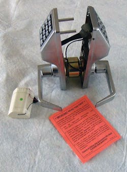
With security becoming a greater concern for people as well as property, the introduction of the Alarm Lock 5300 series dual-sided Trilogy is especially important for protecting fenced perimeters. Non-public areas of day care centers, pre-schools, marinas and commercial businesses require security/access control through their fencing from both sides. For many of these locations, it is inconvenient to use chained padlocks or single-sided deadbolts securing the gates during populated hours..
Adding a dual-sided, battery operated door lock with stand-alone capabilities provides a higher level of security by controlling both entry and exit, and eliminates the need for personnel to unlock and lock. Keyless entry is available with a proximity/keypad equipped Alarm Lock Trilogy PDL5300, and the DL5300 keypad-only dual-sided lock mechanisms.
This Grade 1 mechanical lock incorporates a clutch mechanism to resist forced entry and vandalism. The latch bolt is UL listed and 3-hour fire rated. The electronics are FCC certified. The lever handles are ADA compliant. The Alarm Lock 5300 Series is HIPAA compliant, providing controlled access for securing private health records having time/date stamped reports of door usage.
Note: These weatherproof locks are designed for operational temperature range of -31 degrees Fahrenheit to +151 degrees Fahrenheit (-35°C to +66°C).
The Alarm Lock 5300 Series features six pre-defined User Levels - Master, Installer, Manager, Supervisor, Print-Only and User Codes. In addition, there is a single use Service Code. The Master Code is six digits. User Codes are three to six digits. Up to 2000 individual users can have access using a PIN-code and/or HID Prox card/fob. As an added advantage, Users can be programmed for direction-specific access for one or both sides of the door.
These locks feature real-time clock and calendar, having up to 500 scheduled events. In addition, there are quick schedules for programming the each of these four most common time schedules in one step. A 40,000-event directional audit trail provides a printable record of door access activity by user. The audit trail includes direction of keyless entry door usage. According to Alarm Lock, the time clock allows logging of events to within one second of accuracy.
Programming the 5300 Series locks can be accomplished using the lock’s keypad or a personal computer equipped with Alarm Lock’s DL-Windows or AL-DTMIII Data Transfer Module for PC. On the primary side of the door, there is a data port for programming the lock and querying the audit trail.
Before the installation, the lock was reset, tested and programmed. This permitted training the client on how to operate the lock in the comfort of their office.
Alarm Lock uses the terms primary side housing and secondary side housing to indicate the two halves of the 5300 Series locks. The primary side is the exterior side.
For this article, we installed a DL5300 onto the perimeter chain link fence gate of a child care facility. Prior to this installation, a combination of a mechanical lock and padlock were used to control access. The gate box was tall enough to accommodate the Alarm Lock DL5300. The welder provided anti-tamper protection by welding a plate onto the rear edge of the gate box and a second plate onto the forward edge of the gate post.
Weldable Gate Boxes are available from Keedex for the Trilogy DL5300. The Keedex part number is K-BXSIM. For more information, contact your local locksmith distributor or Keedex, 510 Cameron, Placentia, CA 92870. Telephone: 714-993-4300. Fax: 714-993-4303. Web site www.keedex.com.
Important: Before installing the new lock, make sure the door is operating properly and the closer is functioning. Make any necessary adjustments before installing the new lock.
To accurately drill the mounting holes, I photocopied the template in order to drill from both sides. Having two templates, I attached one to each side and made sure they were in alignment, first by locating each using the existing cross bore opening.
I then drilled the nine pilot holes on each side of the gate box using a smaller diameter drill bit. After the holes were drilled, I checked to make sure they were aligned. Drilling pilot holes makes it easier to drill the larger diameter holes without causing excessive wear to the larger drill bits. Remember to drill the two holes in each side for the rose plate prongs when installing the lock into a metal door.
Important: After drilling the mounting holes, use a drill mounted grinder to remove any burrs and smooth the holes’ edges. This prevents the wire’s insulation from being cut and the lock grounding out.
I removed the lever from the secondary housing, and disassembled the two halves. Then I removed the lever from the primary housing and adjusted for the gate box thickness. Install the primary side lever.
I then “dry fit” the DL5300 onto the gate box to check thickness adjustment and make sure the holes were at the proper locations.
The battery pack was installed into the secondary housing and the battery wire was connected.
The latch was mounted and the screws were just started. This permits easier installation of the lock body housing because sometimes welded boxes make installation difficult.
Next, run the ribbon cable through the one inch diameter holes to the inside. Run the motor wire through the 2-1/8” cross bore holes.
Once the lock body of the primary side is slid into the cross bore holes, make sure the latch tail slides into the retractors. The latch tail should be well within the retractor to ensure proper operation.
Position the motor wire through one of the slots in the secondary rose plate and install the rose plate using the two Phillips pan head screws. Once the screws are secured, test the mechanical operation of the lock using both levers. Tighten the latch screws.
Install the secondary mounting plate using the four provided screws. The ribbon cable should slide through the opening without binding. The motor wire must be slid behind one of the tabs.
Slide the secondary housing onto the lock body and connect the motor wire and the ribbon cable. Once the body is properly positioned install the two mounting screws. Attach the secondary side lever. Test the mechanical operation of the lock.
Test the electronic operation of the lock. Once the lock is operating properly, install the two secondary side mounting plate screws.
With this number of scheduled events, users, audit trail and lock features, the Alarm Lock DL5300 will provide many years of access control.
The DL5300 is equipped with a battery box that uses five AA alkaline batteries. The typical operational life of the PDL5300 batteries is 60,000 cycles and the DL5300 batteries is 100,000 cycles for the average five-day operation company. The typical battery life for the DL5300 is 400 entries and exits per work day for one year.
The dual-sided 5300 Series locks are available in two lever styles and five finishes.
For more information, contact your local locksmith distributor or Alarm Lock Systems, Inc., 345 Bayview Avenue, Amityville, NY 11701. Telephone: 800-252-5625. Web Site: www.alarmlock.com
Related
Related
Electronics & Access Control
Alarm Lock Systems
July 10, 2017
Door Hardware
Keedex Inc.
Nov. 27, 2007


