Special tools: None
Time to install: Retrofit 30-45 minutes
Warranty: Five years limited
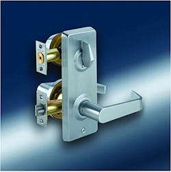
An interconnected lockset can provide the security of a keyed cylindrical lock and singled-sided deadbolt with the added advantage of single action egress. Rotating the interior lever handle retracts both the deadbolt and the lever latch, permitting the door to be opened. Rotating the exterior lever only retracts the latch.
The DORMA J200 Series Interconnected Locksets are based on an ANSI Grade 2 cylindrical leverset and tubular deadbolt. The J200 Series is available with a single lock cylinder deadbolt or two lock cylinders, one for the deadbolt and one for the leverset. The adjustable backset deadbolt has a one-inch throw bolt. The brass bolt is equipped with a spinning hardened steel pin. The deadbolt deadlocks automatically when the bolt is fully extended.
The J200 Series meets ANSI A156.12 Grade 2 and UL/C.U.L. listed three-hour fire rated, A117.1 and ADA requirements for barrier-free accessibility. These interconnected locksets are adjustable to accommodate door thickness from 1-3/8 to 1-7/8 inches.
The connection between the J200 Series deadbolt and the leverset is accomplished through the steel interconnecting plate mechanism mounted onto the interior side of the door. When the deadbolt is locked, pressing the interior lever approximately 45 degrees retracts the latch and the deadbolt, permitting egress.
Note: The interconnecting plate has auxiliary lever springs to ensure the leverset handle remains in the correct horizontal position.
The keyed deadbolt and optional keyed leverset are equipped with six-pin tumbler machined brass lock cylinder having the SC1 keyway. Keying options include interchangeable core and patent pending cylinders.
The J200 Series Interconnected Locks require two cross bore openings located 4 inches apart at their centerlines. The leverset and deadbolt require a 2-1/8-inch diameter cross bore and 1-inch edge bore openings.
Installation of the DORMA J200 Series Interconnected Lockset is straight forward. However, care must be taken to ensure that, when pressed, the interior lever will retract both the extended deadbolt and the latch.
The interconnecting plate contains a slider that moves up as the interior lever is rotated. The driver bar slot (hub) in the plate has an extension that must be at an angle in order for the slider to retract the deadbolt as the inside lever is being rotated.
Depending upon the lock installation, left or right hand application, the extension must cover either the left or right dead bolt mounting screw opening. The left hole must be blocked for Left Hand (LH) and the right hole must be blocked for Right Hand (RH). If not, the deadbolt will not retract when rotating the interior lever.
When installing the J200 Series lockset. it must be properly timed:
Step 1. Drill and prepare the openings for installation. Note: Two anti-rotation 5/32-inch diameter openings must be drilled along the horizontal centerline of the exterior side of the leverset cross bore.
Step 2. Install the bolt and latch into the edge of the door.
Step 3. Slide the leverset assembly onto the latch mechanism from the exterior side of the door.
Step 4. Place the interconnecting plate onto the interior side of the door.
Step 5. Attach the two leverset mounting screws. Do not tighten.
Step 6. Slide lever driver over the interior lever spindle. The side of the driver with the two legs slide into the openings in the interconnecting plate. The single long leg is on the side of the inside lever spindle opposite of the lever catch. The lever driver connects the lever to the interconnecting plate mechanism.
Step 7. Extend the bolt.
Step 8. Turn the driver bar slot (hub) towards the lock edge of the door. This times the lock mechanism. If positioned opposite, the bolt will not retract.
Step 9. While holding the deadbolt lock cylinder on the exterior side of the door, rotate the tailpiece towards the lock edge until it stops. The tailpiece should be vertical. This times the lock mechanism. If rotated in the opposite direction, the tailpiece will not rotate, not allowing the bolt to retract.
Step 10. Insert the deadbolt having the tailpiece slide through the bolt hub and the interconnecting plate hub.
Step 11. Attach the two dead bolt mounting screws through the interconnecting plate. Do not tighten.
Look at the “L” and “R” holes on the interconnecting plate. The hole closest to the lock edge of the door should be covered. This indicates the lock is properly timed.
Step 12. Insert the key into the deadbolt. Retract and extend the bolt using the key.
Step 13. Place the inside lever over spindle and onto the lever driver. The long leg should slide into the opening at the base of the lever. Rotate the lever to retract the bolt and latch. Remove the lever form the spindle.
Step 14. Tighten the four mounting screws securing the leverset and the deadbolt.
Step 15. Slide the inside escutcheon onto the interconnecting plate. Install the two mounting screws.
Step 16. Install the inside lever. Test the operation of the lock.
The standard latch bolt and deadbolt combination is a 1 x 2-1/4-inch square front with a 2-3/4-inch backset. The standard deadbolt is adjustable to a 2-3/8-inch backset. Latch and bolt options include radiused corners and a 2-3/8-inch backset.
The DORMA J200 Series Interconnected Locks are available five lever trim designs and up to four standard finishes depending upon the lever. For interior application leversets, use the DORMA C400 Series locks.
For more information, contact your local locksmith wholesaler or DORMA Architectural Hardware, Dorma Drive, Reamstown, PA 17567. Telephone: 800-523-8483. Fax: 800-274-9724. Web site: www.dorma-usa.com.


