LCN’s 4040 non-sized, cast iron body and forged steel arm door closers were developed to accommodate the demands of heavy traffic applications in institutional environments. The LCN 4040XP is the second generation door closer designed to withstand even more rigorous applications. To accomplish this, LCN has increased the size of the pinion (spindle) shaft and bearing size to ¾” diameter extending 5/8” above and below the closer body. This increases the pinion teeth size and surface area to have 44 percent more bearing load. These and other changes increase the operational life when combating forced openings and closings as well as component misalignment, according to LCN.
LCN 4040 and 4040XP door closers are designed for interior doors up to 5’0” and exterior doors up to 4’0”. They meet ANSI Standard A156.4, grade one requirements for door closers and are UL listed.
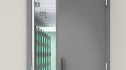
I was invited to the installation of an LCN 4040XP Door Closer onto a four foot wide hollow metal door installed onto a concrete filled metal jamb. This 16-gauge thick skin door has reinforcement for the door closer and the mortise lock.
This outswinging door is located on the exterior of an employee services building. This entrance door accommodates heavy foot traffic 24 hours a day.
The LCN 4040XP door closer was installed onto the interior (secured) side of the door using the Parallel Arm (P.A.) method. For this installation, sex bolts were installed to ensure the closer would remain securely attached to the door.
A walkway with a slight incline leads up to the door, with a dirt area beginning at slightly less than a 90 degree opening. Without an installed door closer, the door could swing almost 180 degrees. This makes it extremely difficult to install a fixed doorstop.
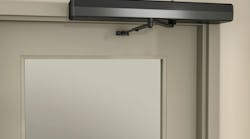
For this reason, the decision was made to install the 4040XP with the Spring Cush Arm. The optional, Spring Cush Arm is a non-handed solid forged steel main arm and forearm. Mounted onto the shoe of the arm is a spring loaded stop. This Spring Cush Arm is designed for heavy traffic and abusive applications.
The 4040XP comes with an EDA arm as standard. LCN also has three Cush arm options that have different types of stops that are mounted onto the shoe. In operation, the Cush arm assembly contact stops the door from swinging beyond a specific opening dimension. The Spring Cush Arm has a spring loaded contact block assembly mounted onto the shoe that uses spring pressure stop to slow and stop the door from opening beyond the installed opening angle.
The degree of opening is determined by the position of the shoe and the door closer body, which is typical of closers with a built in deadstop feature. For the Spring Cush Arm, the closer and shoe can be mounted at up to 11-1/8” from the hinge side of the jamb. The farther away the closer and shoe are located from the hinge side, the smaller the door opening.
Position the door closer template onto the door at the desired swing distance. For this installation, the door swing was determined to be 90 degrees. Position the shoe template onto the jamb, aligning it using the red arrows on both templates.
Use a 1/8” bit to drill four pilot holes in the door and five pilot holes in the jamb. Drill carefully into the jamb as it is extremely easy to dull a hi-speed drill bit when it contacts concrete.
Once the initial holes are drilled into the door and jamb, we used a 7/16” diameter drill bit to enlarge the four mounting holes in the door to accommodate the sex bolts. LCN provided self reaming and tapping screws and machine screws for installing the door closer. LCN developed their own self reaming-tapping (SRT) screws in an effort to eliminate the use of improper drill screws. LCN finds it acceptable to use their SRTs in aluminum, metal and wood door applications. However, LCN still recommends using the available #14 wood screws for wood door applications and drilling/tapping ¼-20 machine screws or installing sex bolts and mating screws in hollow metal and aluminum doors and frames.
Before enlarging the holes in the jamb, a small diameter masonry bit drilled up into the opening to remove some concrete. The locksmith wore a disposable dust mask to protect himself.
Then self reaming and tapping screws were used to enlarge and thread the holes in the jamb. The self reaming and tapping screws were used to just drill and tap the jamb. A larger masonry bit, smaller than the opening created by the self reaming and tapping screw, was used to remove additional concrete in order to install the shoe. Self reaming and tapping type screws are not designed to drill out concrete.
Before mounting the closer onto the door, the valve on the rear of the closer body was closed by turning the hex screw clockwise. This valve controls the position the backcheck function begins to engage.
The closer body was installed onto the door using the four sex bolts. If the holes are slightly out of alignment, try using a long, narrow blade screwdriver to reposition the threaded opening in the sex bolt. Depending upon the content or absence of content in the door cavity, it may be a good idea to use a thread adhesive to secure the mating screws to the sex bolts. Because of the re-enforcement within the door cavity, the four mating screws could be tightened and not alter the shape of the door.
Once the closer body has been installed onto the door, the pinion must be pre-loaded to accommodate the splining in the arm. Attach a wrench or pliers onto the lower end of the pinion. Rotate the pinion clockwise approximately thirty degrees to align the arm opening with the pinion teeth. Once aligned, use a rawhide or rubber mallet to tap the arm onto the pinion. Install the Phillips Head pinion screw.
The next step is to test the operation of the door closer. Open the door at least 90 degrees and permit it to close. Repeat this several times. If the door does not latch or closes very slowly, there is a power adjustment on the end of the 4040XP closer.
Note: Depending upon the location of the door, the closer may be required to accommodate Americans with Disabilities Act requirements.
There are four adjustment set screws on the 4040XP Closer closing power adjustment, backcheck, main (sweep) speed and the latch speed. To increase the closing power, adjust the 5/32” hex screw clockwise. A patented plastic power indicator was attached to the spring tube of the closer body. The default setting was “3”, sufficient spring power to close and latch the door.
The closing time for standard applications is approximately five to seven seconds. About three to four seconds for sweep and three seconds for latch. To increase the sweep speed or the latch speed, turn the 3/32” hex screw on the front of the closer counterclockwise. See the drawing on the tube of the closer to determine the locations for adjustment. Make the necessary adjustments. Keep in mind that the spring adjustment controls the closing force. The regulating valves control the closing speed.
The final adjustment is the backcheck. The purpose of the backcheck is to slow the opening force before the closer reaches maximum opening. To slow the opening force the backcheck can adjust the amount of fluid movement as the door reaches maximum opening.
IMPORTANT: The Spring Cush Arm function does not replace the backcheck. Do not weaken or completely loosen the backcheck setting on the door closer. The Cush functions with the backcheck to slow and stop the door opening.
For this installation, the door closer is equipped with the Spring Cush Arm. This type of arm has a contact block assembly screwed onto the shoe. The handing of the door determines the position of this assembly. As the door is opened, the arm swings under the shoe and the backcheck begins to slow the doors opening.
The contact block assembly mounts beneath the shoe, in the path of the arm. When the door swing is within approximately 10 degrees of the installed opening, the arm contacts the block. As the door continues to open, the arm presses against the block, which moves against spring pressure, further slowing the opening of the door until the block stops the arm from moving.
The backcheck should be adjusted to match the movement of the arm.
Once the backcheck is adjusted, test the operation of the door closer to ensure proper operation.
LCN has developed a snap-on plastic cover for the 4040XP door closer. There is a clip that is snaps on to the closer body tube. There are two cutouts for the pinion and the clip, depending on the hand of the door. LCN recommends locating the clip in the proper cut-out, then “snapping” the cover directly onto the closer body. When the installation is completed, write the date of installation onto the door closer body. This way, should the closer need repair, you will know if it is still under warranty.
LCN 4040XP door closers are available with a powder coat finish, plated finish on the arms fasteners and metal cover as well as a SRI primer with powder coat finish for installation in corrosive conditions. The snap-on plastic cover is standard; the metal cover is optional.
For more information, contact your local locksmith distributor or LCN Closers, 121 West Railroad Ave., Princeton, IL 61356. Telephone: 800-526-2400. Fax: 800-248-1460. Web Site: www.lcn.ingersollrand.com.