Profiting From Gate Operator Installations
Gate operator projects typically present a variety of challenges. If you have performed service on gate operators or have previously installed them, you probably have more experience than most of your competitors.
MECHANICAL
Generally the gate to which you are installing the operator is in good condition. Hopefully it will be a new installation, and the gate has not been hit by trucks and fallen trees and barely opens. Gate operators are forgiving and work great, but a damaged gate that drags will trip the overload on the gate operator and you will waste valuable trying to grease the wheels on the gate.
If the gate and the operator are both being installed within the same timeframe, be sure to clearly state as a condition that the gate must be prepped to the installation spec you submit, and then try to be involved enough so you won’t be in for a big surprise when you show up installation day. Prep work involves setting a concrete pad upon which you will mount the gate operator, and electric conduit to provide the operating voltage and several circuits required for the complete gate operator installation.
ELECTRICAL
You need to be sure the required line voltage feeds are available to your operator. Be sure the electrician clearly identifies the panel and breaker feeding your operator. A local line voltage on/off switch is very handy, but the electricians may charge a steep fee.. Since a lot of conduit used these days is non-metallic, be sure that the electrical circuit is adequately grounded to protect the gate operator, the end-user and you from possible damage from power surges or other anomalities.
ENVIRONMENTAL
Most gates are outdoors and extremely unsheltered. That means you have to take steps to ensure that your equipment is watertight, and does not collect moisture. When water collects, it either seeps into where it doesn’t belong, and causes corrosion and short circuits, or it freezes, expands, and cracks conduit allowing water to enter and seepage to occur. Google the term drip loop.
ELECTRONIC COMPONENTSDue to the fact that the gate is probably isolated from structures and other infrastructure, interfacing your gate operator and associated accessories will most likely present you with some decisions to make.
My installs usually involve a card reader, intercom, remote release, video surveillance, safety and approach sensors, and voltage drop.
Card readers use a Wiegand interface. When a card is presented to the reader, a serial data stream is sent from the reader to the access control circuit board. Depending on the reader, an excessive length of the cable between the reader and the controller may become a problem resulting in inconsistent reader operation.
Gate operator access control will frequently require an intercom link between the gate and a guard station or other location within the facility where the gate is remotely controlled. Since the gate is outside and there may be high levels of ambient vehicle or wind noise, special consideration should be given to intercom selection.
In many situations it is desirable to view individuals who are requesting access through a controlled vehicle gate. A camera designed to provide the desired image (the driver’s face, or perhaps the vehicle’s plate number) must be selected.
Gate operators are required to be equipped with two types of auxiliary control sensors referred to as approach sensors and safety sensors. Approach sensors can be magnetic detection loops buried into the pavement adjacent the gate. Safety presence sensors are situated under the pavement under the gate itself. Other types of motion and presence sensors may be used above ground, thereby making the labor intensive burying of sensor loops unnecessary.
SAFETY FIRST
The standard to which vehicular gate operators are designed, manufactured and tested is UL 325; Underwriters Laboratories Inc., Standard for Safety: Door, Drapery, Gate, Louver, and Window Operators and Systems.
In addition to the 325 standard, vehicular gate operators must also be tested to UL 991; Tests for Safety-Related Controls Employing Solid-State Devices. The UL 325 Standard has undergone significant revisions over the past several years. The purpose of the revisions is to create entrapment prevention criteria for vehicular gate operators and systems, and to increase over-all safety of the product.
The standard also calls out for specific construction specifications for the vehicular gate itself (see ASTM F2200-02). The revised standard was first published Sept. 18, 1998, and went into effect March 1, 2000.
Secondary entrapment prevention device or devices are installed in areas where an entrapment hazard exists. These devices include contact (electric edges) and non-contact (photo-electric) sensors.
Warning signs are placed in an area where they are visible from each side of the gate.
Gate controls are installed in such a manner that a person operating the controls cannot come in contact with the gate or gate operator.
The gate operator needs to be appropriate for the construction and class of the gate. Rollers should be guarded. Pinch points should be eliminated or guarded.
All openings in slide gate systems are guarded or screened from the bottom of the gate to a minimum of 48 inches above the ground to prevent a 2.25-inch diameter sphere from passing through the openings anywhere in the gate, and in that portion of the adjacent fence that the gate covers in the open position.
Refer to ASTM-F2200-02 for more information on the construction of the gate and associated hazards.
DOORKING 9100
The Model 9100 sliding gate operator is designed to operate vehicular slide gates in residential and commercial applications. It can easily be mounted in the front, center or rear of the gate without any costly and time consuming field modifications. In addition, the operator can be pad- or post-mounted to meet any installation requirements.
DoorKing vehicular gate operators have been designed to exceed the requirements set forth in UL 325 with their mission statement to offer the safest vehicular gate operators on the market.
Besides offering reliable products with a five-year warranty, DoorKing provides top shelf live tech support and exhaustive documentation that will never leave you out in the cold, (or heat). Features include:
Self-adjusting, no maintenance magnetic limits.
Partial-open feature.
Anti-tailgating feature.
Gate tracker reporting output.
Ports for plug-in loop detectors.
Two convenience outlets.
Fail-safe release (fail-secure optional) .
Programming switches.
Built-in reset switch.
Built-in power On/Off switch.
Specifications for the Model 9100 include:
Maximum gate length 30 feet.
Maximum gate weight 1000 pounds. (Assumes gate is on level ground, in good condition with properly adjusted hardware. Other external factors may affect the performance of the gate operator.)
1/2 HP continuous-duty motor.
115 VAC, 5.4 Amps.
Operator is shipped with chain brackets and 20-feet of #41 chain.
Class I, II, III and IV applications.
Compliant with UL 325 and 991.
Dimensions: 12”W x 24”H x 11.5”D.
DOOR KING microPLUS®
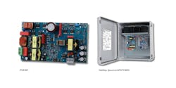
DoorKing MicroPLUS RF controls provide a high level of security because coding and encryption schemes are unique to DoorKing, resulting in transmitter codes that cannot be duplicated or copied. Therefore only the original intended transmitter will activate your access system. The 8056 ‘looks’ like any other Wiegand reader, and the transmitters are managed (enrolled deleted, tracked) just like any other credential.
PROXmitters combine RF control with a proximity tag to provides remote operation of vehicular access gates from the safety and convenience of a vehicle.
MicroPLUS® transmitter codes cannot be copied assuring that only the original intended transmitters will activate the access control system. More than 286 million transmitter codes are available plus an encrypted “sync” code that changes every time the transmitter is used.
Features of the 8056 receiver include:
Weigand output receiver.
Supports up to 5300 transmitter codes.
Output data in 26, 30 or 31 bit formats.
12-24 volt, AC or DC.
MicroPLUS Transmitter features include:
268,000,000 codes available.
Encrypted “sync” code changes each time the transmitter is used.
Transmitter button combinations allow a single transmitter to control multiple locations.
PROXmtr™ includes a built in proximity card with the MicroPLUS transmitter combining both RF and card access control into a single compact unit.
Transmitters are available with one, two or three buttons.
MicroPLUS® RF controls may be used as a standalone access control system or can be interfaced with 26, 30 or 31-bit Wiegand Controllers
Capacity is:
Model 8054: 50, 100, 250, 500, 1000, 1250 transmitters
Model 8055: 40 transmitters
Model 8056: 5300 transmitters
The Model 8054 standalone receiver can support up to 1250 transmitters and stores the last 2300 transactions. Serial printer can be connected to print transactions as they occur, or can print transactions stored in the history buffer. Receiver features 10 programmable time zones, built in clock/calendar and a built in keypad for easy programming.
The Model 8055 standalone receiver can support up to 40 transmitters. Programming is by means of the receiver “learn” method. Individual transmitter codes cannot be deleted from this receiver.
Model 8056 sends the received transmitter data to an access controller in 26, 30 or 31-bit Wiegand formats. It supports up to 5300 transmitters and is designed for interface with access controllers such as the DKS 1833, 1835, 1837, or 1838
Transmitters have 268,000,000 codes available. Encrypted “sync” code changes each time the transmitter is used.
Transmitter button combinations allow a single transmitter to control multiple locations. They are available with one, two or three buttons PROXmitters - same as the standard transmitter and include a built-in proximity card. PROXmitters are available with DKS, AWID, or HID tags. Button combinations allow two- and three-button transmitters to control multiple devices.
Operating temperature ranges are -10ºF to 115ºF, -23ºC to 46ºC
Electrical Requirements:
Receivers - 12-24 volt AC or DC power
Transmitters – 12 Volt type 23A battery
Output
Model 8054 receiver – Dry contact form C relay (30V, 1A max)
Model 8055 receiver – Dry contact form C relay (30V, 1 A max)
Model 8056 receiver – 26, 30 or 3-bit Wiegand
BEA REMOTE CONTROL
With the BEA 1S40 dual tech motion presence sensor & programmer, active infrared and microwave technologies work together to provide precise presence and accurate motion detection in front of the door. However, the IS40 is priced competitively with other microwave-only products.
Its maximum mounting height is 16 feet, and the detection pattern includes up to 40 spots, equating to 10-foot by 10-foot coverage. I mounted mine at about seven or eight feet high and the product worked very well.
It is impervious to door vibrations, light, sun and the environment; including rain and snow. The IS40 housing is rated NEMA-4.
I mounted my unit on a metal pole that vibrates whenever the gate is operated, and the field of view is full of tree branches. The BEA remote control works perfectly, and provides enough variables to tune out nuisance issues while still maintaining excellent capture.
The IS40 can be set for detection of one direction movement (towards or away) or both. I found aiming the unit rather intuitive and the sensor’s response to tuning with the remote made tweaking fun and productive.
This unit replaces the labor-intensive inductive loops or obsolete technology microwave sensors with an easy-to-mount overhead installation. All adjustments are executed using the BEA remote control. The unit has a three-year (not one year) warranty, and plenty of aggressive technical support.
Tim O'Leary
Tim O'Leary is a security consultant, trainer and technician who has also been writing articles on all areas of locksmithing & physical security for many years.


